Eng-Tips is the largest engineering community on the Internet

Intelligent Work Forums for Engineering Professionals

Pipe draining back to tank 1

Status
Not open for further replies.

Sparky4598

Mechanical
May 4, 2024
16
0
0
US
I am struggling to figure out if a closed loop pipe system could drain all or even some of the fluid out of the pipe back into the reservoir after the pump shuts off.

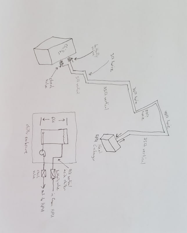
Fluid is 50/50 propolene glycol / water. The system is a chiller fluid system. The reservoir is a vented tank. The pump pulls fluid from the tank, up 40ft vertically and into the building, horizontally about 150ft, down 35ft to a sealed heat exchanger, and back up and out to the tank outside the building. So the inlet and outlet of the pipe system is at the same elevation.

I originally thought there is no way it could drain out as long as no air is in the pipe or enters the pipe some way. But then I thought could the weight of the fluid cause enough of a pressure drop at the top of the pipe to cause the fluid to boil and allow some of it to drain back and overflow the tank after the pump is turned off. EDIT: There is 1 butterfly valve and 1 check valve that closes when the pump turns off.

If I left out any details necessary, I Apologize. Just let me know and I can add any info necessary. Thanks!
 
Replies continue below

Recommended for you

I would assume if the total volume of fluid in the system is larger than the volume of the tank, it has the potential of overflowing. In your case, I imagine it could burp air bubbles up the piping as the fluid fills back into the tank. Or siphon its way through.

On a design I worked on, the skid manufacturer made absolutely sure that the total fluid in the system did not exceed to capacity in the tank, even though there were check valves to hold the fluid in the piping. Said design was also a glycol loop with a vented tank.
 
Total fluid volume is about 500gal and the tank volume is 100gal. That may have been a detail I left out, the inlet and the outlet of the chiller is very near the floor. Inside the chiller unit, the pump of course siphons from the bottom of the tank and the return enters the tank approximately 2/3 up the tank from the floor. Unless I am mistaken, I don't see how it could burp or siphon and air or fluid.

There is an automatic butterfly valve installed on the return to the chiller and a check valve on the outlet. The butterfly valve opens after the pump turns on and there is a significant shock that rattles the pipes through the building when the pump kicks on. I want to remove the check valve and move the butterfly valve to the outlet instead of the return, but the manufacturer claims the pipe system would drain back if we do that. I cannot wrap my head around how that would be possible.
 
You need to sketch this out in cross section / elevation as I'm having difficulty following the path. Your use or return and outlet is confusing as this sounds like the same thing... Outlet of what? Where is the chiller i all of this?

I think you have an inverted U by the look of it, but its not easy to say.

If so a portion might well drain down but only a little bit which when the pump starts collapses with large shock waves.
A non return on the outlet of the pump would seem a good idea.

But give us a sketch with elevations and we might be able to figure it out.

Remember - More details = better answers
Also: If you get a response it's polite to respond to it.
 
In your first post you wrote "There are no valves or check valves that close when the pump turns off."

In the second post you wrote "There is an automatic butterfly valve installed on the return to the chiller and a check valve on the outlet."

These two statements seem to be at odds with each other and need to be explained.

Please confirm that the shock the rattles the pipes occurs when the pump starts up and not when the valve is opened. The way I understand it is that the valve is already open when the pump starts. How long is the period betweem the valve opening and the pump starting?

I agree with LittleInch that you need to post a flowsheet showing the location of the items. The outlet of one item can be the inlet of another and your description is confusing without a sketch.

It seems that the plant is already in operation so you know that the 500 gallons in the system do not drain back into the 100 gallon tank completely. Is your concern that it could drain completely if the line breaks somewhere? Does the level in the tank increase at all when the pump stops?

Katmar Software - AioFlo Pipe Hydraulics

"An undefined problem has an infinite number of solutions"
 
katmar said:
These two statements seem to be at odds with each other and need to be explained.
I apologize, the first post was incorrect. I don't know what I was thinking. I have corrected it.

katmar said:
Please confirm that the shock the rattles the pipes occurs when the pump starts up and not when the valve is opened.
The valve is closed when the pump starts. It begins to open when the pump starts and takes approx. 10 seconds to fully open. The shock occurs when the pump starts and the valve is still closed.

katmar said:
Is your concern that it could drain completely if the line breaks somewhere?
I feel that the butterfly valve should have been installed on the outlet of the chiller instead of the inlet of the chiller. By my logic, this would allow the flow in the pipes to gradually increase and stop the shock in the pipes. The chiller manufacturer claims the fluid will drain out of the pipes and overflow the tank if the valves are not installed as they are shown in the attached picture.
I am trying to determine if 1) their claim is valid and 2) if their claim is valid, how is it possible?

littleinch said:
You need to sketch this out in cross section / elevation as I'm having difficulty following the path.
Here is a rough hand sketch of the system. Please forgive me if I did not use the correct symbols and my terrible hand sketching skills. Hopefully it is good enough to get the point across at least.
20240511_092859_yrxtlt.jpg


Again, I want to swap the automatic butterfly valve to the other pipe and remove the check valve.
 
If you were to move the butterfly valve to the outlet of the pump, you would have issues with the system draining as the manufacturer states unless you put something there to hold back the fluid. I suppose you could put a high cracking pressure check valve where the butterfly valve currently is to prevent everything from draining as an alternative.

Regarding the rattling pipes, what is the shutdown procedure? Does the butterfly valve close before the pump shuts off? On shutdown is there any fluid that leaks into the tank past the butterfly valve? Seems like there may be air getting into the section of pipe between the pump and the butterfly valve.

Either way, I would not want to remove the check valve and you will want something on the return to keep the fluid in the pipes.
 
I agree with sentrifice

I suspectthe valve starts closing as the pump is turned off.

That large vertical fall will result in pulling a vacuum in the top horizontal piping and some water going into the reservoir. The band stops the pipe fully draining. When thr pump starts that vacuum collapses with a huge jolt before the valve can open. Moving valves will do nothing for you.

You need to either fit a back pressure regulating valve next to or in place of the butterfly valve or arrange for the valve to fully close first and then turn the pump off only when the valve is fully closed. A few seconds of no flow won't do the pump any harm.

Remember - More details = better answers
Also: If you get a response it's polite to respond to it.
 
Yes, the pump turns off at the same time the valve starts to close, so the pump is off for about 10 seconds before the valve becomes fully closed.

So it sounds like you are saying the height of the riser is enough for there to be a low enough pressure at the top to boil off some fluid and create a gas pocket that allows some fluid to flow into the tank. Then when the pump turns back on and pressure returns to the top of the pipe, the gas pocket rapidly collapses and creates the shock. Is that sort of the correct understanding?

So closing the automatic valve before the pump turns off should be a viable solution?
 
Sparky4598 said:
Then when the pump turns back on and pressure returns to the top of the pipe, the gas pocket rapidly collapses and creates the shock. Is that sort of the correct understanding?

I believe this is the essence of the problem. Judging from your lengths and volumes it sounds like you have a 4" line and that is certainly big enough to cause some violent banging. When the pump starts up it will cause the vapor pocket to collapse and that shock will travel down the line until it hits the closed butterfly valve and then it will bounce back up the line and you will get a nice rattle.

You could try closing the butterfly valve (slowly!) before shutting off the pump so that the line does not have a chance to drain back to the tank and develop the vapor pocket. But it is rare for a non-return valve to seal 100% and if the pump is off for a while the liquid could drain back through the pump and into the tank slowly and still allow a vapor pocket to develop.

I suggest two things to avoid the banging. Firstly, open the butterfly valve before starting the pump. This will prevent any shock that does develop from bouncing back up the line. Secondly, do not start the pump up at full flow. If the pump is on a variable speed drive you could start it slowly and gradually ramp up the speed. Alternatively install another valve between the pump and the NRV to start the pump against a closed head and gradually open it.

Overall I agree with your supplier and I would leave the butterfly valve where it is to prevent accidents if the line ever develops leaks that could allow the ingress of air.

Katmar Software - AioFlo Pipe Hydraulics

"An undefined problem has an infinite number of solutions"
 
"So it sounds like you are saying the height of the riser is enough for there to be a low enough pressure at the top to boil off some fluid and create a gas pocket that allows some fluid to flow into the tank. Then when the pump turns back on and pressure returns to the top of the pipe, the gas pocket rapidly collapses and creates the shock. Is that sort of the correct understanding?"

Yes. It doesn't need to boil off, but the maximum height at sea level of a watercolumn is about 30 ft allowing for some vapour pressure. You're just pulling a vacuum.

So even in operation, this vertical column back to the open reservoir might start to get some two phase flow at the top of the riser.

Actually is the reservoir open to atmosphere?
An alternative would be pressurise the reservoir to maintain a pressure greater than say 5psi at the top when the pump isn't running.

But yes, closing the valve first before turning the pump off might do the trick, but as katmar says, check valves rarely seal 100% for life so a second actuated valve which closes slightly after the first one (say 5 seconds) and only when that valve is closed do you turn the pump off.

On restart do the reverse. So pump on, open pump discharge valve, open return valve. All with a little bit of a gap between if you can.


Remember - More details = better answers
Also: If you get a response it's polite to respond to it.
 
LittleInch and I have given basically the same advice. The only real difference is that he has advised first starting the pump, then opening the new valve on the pump discharge and then finally opening the existing butterfly valve in the return line whereas I have advised opening the existing valve first and then either starting the pump at a slow speed or using the new discharge valve to increase the flow slowly.

Following my advice will cause the vapor pocket to be developed at every start up and then relying on the slow initial flow of the liquid to collapse the vapor safely. Following LittleInch's procedure will prevent the formation of the vapor pocket as long as there are no leaks in the system. As his advice would be easier to implement it is probably the better way to go initially and if it turns out in practice that the vapor pocket formation is avoided then you can continue with it.

You may be wondering why this situation is not well known and why there isn't a standard procedure to prevent the water hammer. The reason is that your height difference is right at the point where vapor pockets start developing. If the height difference were less then no vapor pocket would ever form and there would be no problem.

On the other hand, if the top of the system is much higher than yours then vapor pockets form constantly - even under running conditions - and they need to be dealt with on a continuous basis. The standard way around this is to have an open vent at the very top of the system and this prevents a vacuum from ever occurring. Although this system is very safe and reliable, it does have the disadvantage of using more pumping power because having the open vent at the top means that there is no pressure recovery in the downflow leg. Also, because the return flow is purely by gravity it is usually necessary to use a larger diameter pipe for the return line and ideally it should be large enough to ensure self venting flow.

Another reason for your particular system being problematic is that at the highest point you have 150 ft of horizontal piping and the vapor pocket is likely to extend over this entire distance. In my experience two phase flow is most problematic in horizontal pipes. I suspect this is because in sloped pipes the liquid moves naturally in one direction and the vapor in the opposite direction so that you have a small vapor-liquid interface. Anyway, having a 150 ft long vapor pocket is not ideal.

Katmar Software - AioFlo Pipe Hydraulics

"An undefined problem has an infinite number of solutions"
 
Also at the start you say this is a closed loop system but then say it has a vented tank. That is the key issue here as that means you only have at best a semi closed system.

A true closed loop system would use a pressurised tank such that the pressure at the high point is always more than 0psig.

All your pump then does is circulate fluid.

That's how you can get closed loop systems which are hundreds of feet high and not have this problem.

Remember - More details = better answers
Also: If you get a response it's polite to respond to it.
 
Littleinch and Katmar, thank you both very much for your valuable input! I really appreciate the assistance understanding what is going on in this system.

littleinch said:
Also at the start you say this is a closed loop system but then say it has a vented tank.
Yes, I was thinking of the piping as a closed loop, but I suppose I was incorrect to say the system was closed loop since the tank is indeed vented. In my mind, I was thinking the tank was irrelevant because I was thinking of water as an incompressible fluid, but that does not necessarily mean it is inexpandable. I was forgetting about vacuum and the potential for a vacuum bubble to form.

I will suggest the manufacturer change the control logic to fully close the butterfly valve before turning off the pump. I will also suggest a soft starter be added since the pump is currently fixed speed off or on or that a second automatic butterfly valve be installed on the pump outlet.

I will report back once we have a resolution to the issue.

Thank you again for the help!!


Suspect your PPEG return to the tank is currently ABOVE the normal liquid level, which is what is causing the return leg to drain out partially ( at least until the automated butterfly valve closes) on pump stop - air reverses back up this line to break the partial vacuum. And your tank is open vented.
Relocating this PPEG return to be BELOW minimum tank level may resolve this. You then wont need the automated butterfly valve. Keep liquid level in the tank some 4 to 6inches at least above the relocated return line.
 
Lower flow will result in more problems. At lower flow you will end up with two phase flow in your horizontal section as the flow out into the tank will be more than flow in for a while as the vertical leg drains out with a vacuum in the line.

If you're going that route (lower flow) fit a back pressure control valve in place of the butterfly valve to maintain about 25psi at the entry into the tank.

Remember - More details = better answers
Also: If you get a response it's polite to respond to it.
 
The real root of the problem is the unnecessary 35 ft rise and drop in the piping. It has probably been done that way to keep it out of access ways and to look neat, but if it could be re-routed without the rise and drop the whole problem would go away.

Katmar Software - AioFlo Pipe Hydraulics

"An undefined problem has an infinite number of solutions"
 
Katmar,

I agree, but the reality is that almost certainly a lot harder to fix than a few valves or a pressurised reservoir.

George, the issue is the vertical drop (35 feet) though it may be exasperated by air entering from the bottom if the pipe isn't submerged. but submergence isn't the answer here, just lessens the effect maybe.

Sparky 4598 - "I was forgetting about vacuum and the potential for a vacuum bubble to form."
Exactly - and so did whoever did the routing - was it you?

Remember - More details = better answers
Also: If you get a response it's polite to respond to it.
 
In cold PPEG/water, there is hardly any volatiles for flash gas to break out at the top to break a possible vacuum. In the current setup, the downward descent section is most likely not fully liquid filled - it is part liquid, part air. So there is no sub atmospheric conditions in this downward section.
 
Flow Rate = Q = Unknown
Friction loss in piping = H[sub]L[/sub] = unknown
Friction loss in upward flow = H[sub]L[/sub]/2
Friction loss in downward flow = H[sub]L[/sub]/2

System High Point = 40ft
Density of 50/50 solution is 64.8 pcf,
40ft column has a pressure of 18 psi

Pump head required = 40ft + H[sub]L[/sub]
(Including 40ft pipe filling capacity at max flow rate, maybe not be entirely required)

WHEN PRESSURE JUST UPSTREAM OF VALVE IS LESS THAN 19 psia (4 psig),
You will be reaching 0 psia in the high piping, 18psia - 18 psi weight of fluid column.
The high piping will be vaporizing, or in other words, not be flowing full.
The "empty" space in the pipe will be filled with a mixture of water/glycol vapors.
That's OK when the pump is running stable, but any pressure increase will fill the pipe with liquid again and you will get a vapor collapse shock. So, if nothing increases pressure in the system, no worries. The hammering only happens when the pipe transitions from partially full to full.

Your problem seems to be occurring at pump start. Probably because during the previous operating phase the system was not flowing full when the pump shut down. That left a vapor pocket in the high piping and some portion of the downcomer. Your check valve prevented draining of the upward flowing pipe. From the above analysis, that means that the pressure just upstream of the butterfly valve was less than 3 psig, (18 psia) when the pump shut down and the valve closed. 18 psia - weight of a full liquid column, also 18 psi = 0, indicating vapor space is probably being created in the high piping. If the valve pressure is less than 3 psig, then empty space is also in the downcomer.

Now when the pump is started again, pressure increases everywhere and the vapor space is collapsed, causing your hammer shock. To stop that from happening, the pump must be shut down when the pressure at the upstream side of the butterfly valve is above 18 psia, 3 psig. The higher, the better. I'd suggest you try closing the butterfly valve when it has a pressure of 20-25 psia, or 5 to 10 psig. Then you will know that the pipe is flowing full when it is shut down. If pressure holds, then you know the pipe remains full and it will not be subject to vapor collapse hammer effect when the pump is restarted.

If you do not have a pressure gage just upstream of the valve, tell me where you do have a pressure gage installed and I can tell you the minimum shutdown pressure you need to see on that gage (provided that you do the following).

If you can post the operating flow rate range, pipe diameters, wall thicknesses, pump curve, then we could have a proper understanding of exactly what is happening. Until then, that's my best guess.

Probably just easier to close the valve when the pump is running and very quickly shut the pump off.


--Einstein gave the same test to students every year. When asked why he would do something like that, "Because the answers had changed."
 
Status
Not open for further replies.
Back
Top