Eng-Tips is the largest engineering community on the Internet

Intelligent Work Forums for Engineering Professionals

pipe failure 2

Status
Not open for further replies.

Sergio76

Mechanical
Apr 11, 2012
28
0
0
US
20140827_113712_a4ags1.jpg

VRT-photo1_zscql4.jpg

VRT-photo2_b7oubm.jpg

jrs_phone_080_ks1yct.jpg

jrs_phone_078_eq1syw.jpg

jrs_phone_079_nmnyqy.jpg


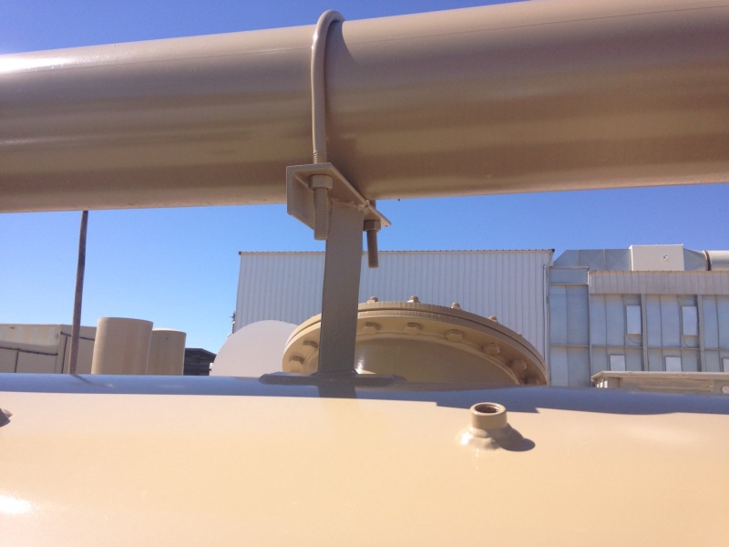
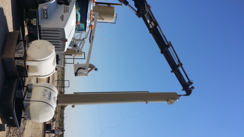
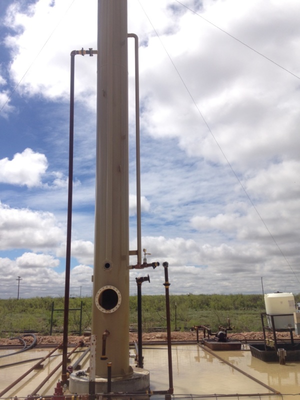
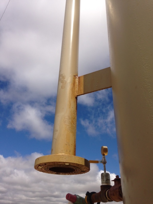
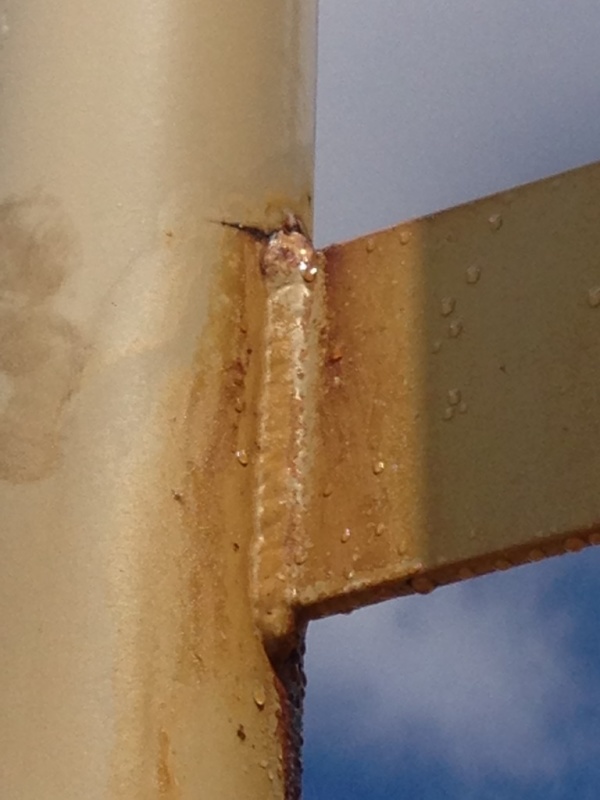
Hello all, I have some equipment as shown in the pictures that have a pipe failure at the support attached.
This is a Vertical Recovery Tower 30" OD X 30' S/S operating at 50 PSI @ 100 F. According to the field foreman, the vessel started leaking 30 min after operation start.
my concerns about this failure were:
1.Transportation and erection procedure, but apparently all pipes are free from any erection load.
2.Material of origin, I checked the MTRs, and the material is according to SA-106,B Smls pipe.
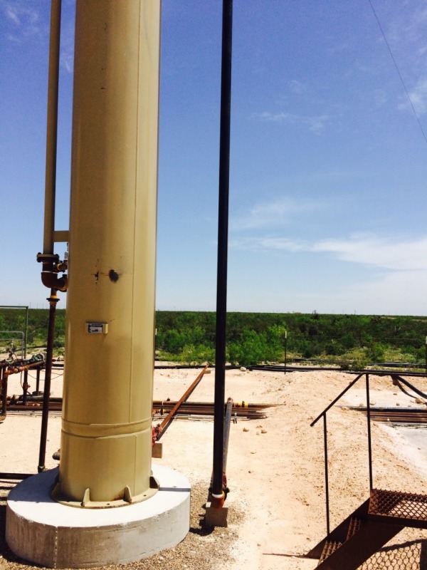
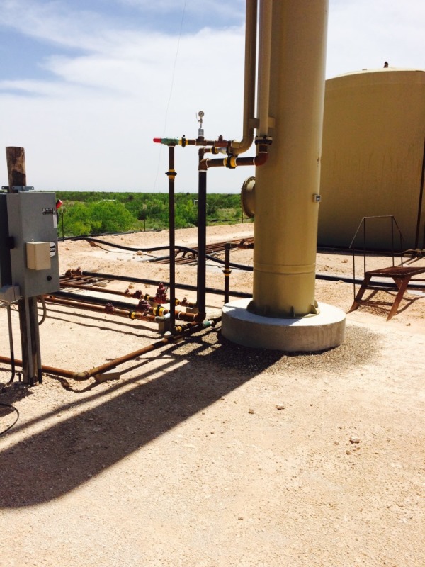
3.Looking at the pictures, there appears to be pipe hanging off of the vessel connections and the pipe is supported by bricks, not concrete foundations. These foundations are probably not offering any support, vertically nor laterally. The pipe seems to be just resting on the bricks. I think it could be a vibration problem, because we cannot see where the pipes go. I suggest the customer should have poured concrete bases for the pipe supports, then secure the pipe with brackets and u-bolts. I think the customer’s pipe is not adequately supported and there must be some type of oscillating load. The failure look like fatigue, normally seen at a compressor station.

I have not be exposed to much to this kind of failures, I would appreciate if someone could guide me to figure out what could be the possible cause of this pipe fracture.
thanks a lot.
 
Replies continue below

Recommended for you

Is there any temperature difference between the pipe that failed and the tower? The pipe is fixed both at the top and bottom, and there is little to no flexibility provided. If there were any differential thermal expansion between the pipe/column, this could lead to a failure.

 
After review of the pictures, it would appear that the crack emanated from the toe of the structural attachment weld and is probably caused by mechanical fatigue. I would suspect you had localized bending forces acting on the column from the pipe support based on the crack orientation and location.
 
This appears to be a case of VERY bad design done by really inexperienced people.

Management always seem to claim experts cost too much, but look at what amateurs did here. Now consider the cost for this repair plus the cost of lost production.

One expert would have seen this while in the early design stage and corrected it.

Sometimes its possible to do all the right things and still get bad results
 
I would go for the expansion stress and possibly other static forces hanging off that flange. Also from the photos it doesn't look like the tower has been bolted down??

The axial single attachment is very poor design and shows a lack of design knowledge about how to support and not stress pipe. At that diameter and length it could also start to vibrate from wind vortex.

classic stress concentration failure in my book. Just as well it leaked before it completely failed...

Remember - More details = better answers
Also: If you get a response it's polite to respond to it.
 
good morning all, and thanks for your inputs...some answers to your questions and comments:
Marty007, there is not really a temperature difference or thermal expansion, the pipe has only one support at bottom close to the flange.
Metengr, I am agree with you as I mentioned it looks like due a fatigue, caused by pipe oscillation due to a lack support.
Spoonful, yes the vessels were hydro.
Littleinch, you are right, it looks like the tower is loose from the concrete slab, however I need to figure out if this is the operational configuration or if it was unbolted just because this unit is out of service. You bring a good point here "vibration from wind vortex"
Mechanical2014, I think the weld looks good, I don't know about the procedure or the weld quality, however the field foreman mentioned that point, maybe this is caused by overheat during the welding procedure.

I am agree with all of you guys in that the design is poor an inadequate, some of my solutions are:
1. As I mentioned pour concrete bases and anchoring the pipe with U-bolts.
2. Add a piece of plate as a repad to the support at the pipe side, this vessel is internally coated, so ideally I will add a pad at both sides to the pipe and to the vessel, but the customer do not want to affect the internal coat.
3. the customer suggest a solution as shown in the picture, which I think it would work, but really is important to understand what is causing this fail, because if this is for an extra load at the bottom, with this solution the load is going to transfer to the elbow or the vessel connection at top. in this pic you could see what I am proposing in (2)above a pad but at the pipe side.
IMG_0686_bmpich.jpg


With your experience guys what will be the best solution to fix those vessels, by the way I have 18 of 50 with the same issue.
 
In the first few photographs by the OP...

That particular pipe support philosophy of welding pipe clips onto both the pipe and the vessel is inviting inevitable failure. To then support everything on sleepers below the first elbow at grade serves to accelerate the process towards the aforementioned inevitable failure.
 
Sergio,

You need to do some sort of pipe stress analysis to determine what can and can't be done and use some proper pipe supports and hangers.

There is simply far too much stress concentration at the weld. At the very least this support needs to have a collar welded to the pipe with circumferential welds and then the support welded to that, NOT direct to the pipe.

in general anchoring things all over the place simply causes more problems - some flexibility and ability to move or expand is usually useful.

I would remove that horrible welded support and replace it with a sliding one guided to prevent too much movement and then on the horizontal leg not support it until a few metres away to give the pipe somewhere to go both horizontally and vertical, basically an L shape. You might not think there is much of a temperature difference, but welding it locks in the temperature in the shop when it was welded. you might need to clamp another support round the main vessel about half way up to provide a guide to allow only vertical movement of the small diam pipe as this is a long flexible bit of spaghetti ad could easily vibrate or resonate due to wind or other vibration source.

given that the areas apparently floods easily, making the supports from concrete rather than a few bricks will help....

BTW that second photo is just about as bad as the first. You can see the movement of the pipe which can become locked up quite easily and will just wrench the support off the vessel or snap the U bolt. This is effectively an anchor point and not a sliding support and to brace it off a vessel.....

I don't know where this is or how the customer is getting away with it, but this is poor design. Make a better design.

Remember - More details = better answers
Also: If you get a response it's polite to respond to it.
 
A detailed analysis of the stresses and moments generated is going to be really important to figure out how much will need to change to repeat it for the other sites, and the part of your first bit where you mentioned 'Supported by bricks' really made me shake my head.

The foundation is definitely the first part of any structure that should be considered, and this customer hasn't considered it at all.

That U-Bolt in the second picture looks like it's under a bit of strain already, more bad news for your customer I'd say.

Hopefully your customer learns some hard lessons here.
 
Snorgy and Littleinch, as I mentioned before, I am agree in that this design is really poor, by the way this is a non code vessel. Littleinch I didn't understand exactly when you say:
"this support needs to have a collar welded to the pipe with circumferential welds and then the support welded to that"
"replace it with a sliding one guided to prevent too much movement and then on the horizontal leg not support it until a few meters away to give the pipe somewhere to go both horizontally and vertical, basically an L shape."
" you might need to clamp another support round the main vessel about half way up to provide a guide to allow only vertical movement of the small diam pipe"

could you show me that graphically?
If this had been my design I would put more supports along the pipe, but as I told you those equipment are in service and we just need to submit a reparation procedure.

as always thanks a lot.
 
to clarify the picture showing the U bolt, this is not implemented yet as a repair procedure, the customer just come out with this idea as they did that type of brace for a firetube stack, we want to provide the better solution to be free of future issues and to provide a better design for future orders.
 
The causes and remedies have already been thoroughly addressed, so I just want to add a moral to the story: there is no such thing as a non-load carrying weld.

"If you don't have time to do the job right the first time, when are you going to find time to repair it?"
 
Free engineering!

Ok here's a pretty crappy sketch, but I think it gets the principles across.

You do need to do some stress analysis though to make sure the top connection can handle the static weight. in most circumstances it is always best to allow the piping to move a little, but in a controlled manner rather than lock it all in with anchors and clamps

Remember - More details = better answers
Also: If you get a response it's polite to respond to it.
 
 http://files.engineering.com/getfile.aspx?folder=ecb0f9db-2b83-44b1-a866-17752e9ea9a6&file=CCF01052015_0000.pdf
Littleinch, thanks and thanks a lot for your suggestions, I will perform a FEA to figure out what are the critical points, and from them I will suggest the better and most economical solution.

if someone else have another idea, please share with me.
thanks to all
 
Crap drawing. Guides onlY, no limit stops.

You should only need stress analysis not fea.

Remember - More details = better answers
Also: If you get a response it's polite to respond to it.
 
Nothing wrong with limit stops, properly gapped. If gapped closely, my only suggestion then would have been one in-plane and one out-of-plane offset with a trunnion support on the downcomer somewhat below (reasonably close to) the top nozzle. That would ensure that the pipe hangs correctly without imparting a big moment on the nozzle; there would be some torsion though; probably not much if properly designed.
 
Sergio76:
Look at your first photo, I suspect that the primary reason that pipe support is there is because that particular pipe, down to the flange, ships as part of that main vessel. It would break off at the upper elbow if it was just allowed to wag in the breeze during transit. Your later pictures show vertical pipes just as long and just a large/heavy, which do not seem to need that welded support plate. You say it was hydro. tested at the manuf’ers. plant, and leaked before the vessel really went into service. So, when and how did the leak and cracking likely happen? In your third photo the piping below the flange is much huskier/stiffer on the pipe that cracked, if that lower pipe exerts any force on the cracked pipe at the support. That is really a pretty feeble pipe support detail in its strength and welding, and it’s not too surprising that the pipe cracked the way it did. What are some of the loads, potential pipe movements, sizes, thicknesses, etc. around that pipe support? Show us a well proportioned sketch of those pipe details. Show us the orientation of the vessel and that pipe during transit.
 
Status
Not open for further replies.
Back
Top