Eng-Tips is the largest engineering community on the Internet

Intelligent Work Forums for Engineering Professionals

pipe failure 2

Status
Not open for further replies.

Sergio76

Mechanical
Apr 11, 2012
28
0
0
US
20140827_113712_a4ags1.jpg

VRT-photo1_zscql4.jpg

VRT-photo2_b7oubm.jpg

jrs_phone_080_ks1yct.jpg

jrs_phone_078_eq1syw.jpg

jrs_phone_079_nmnyqy.jpg


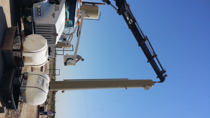
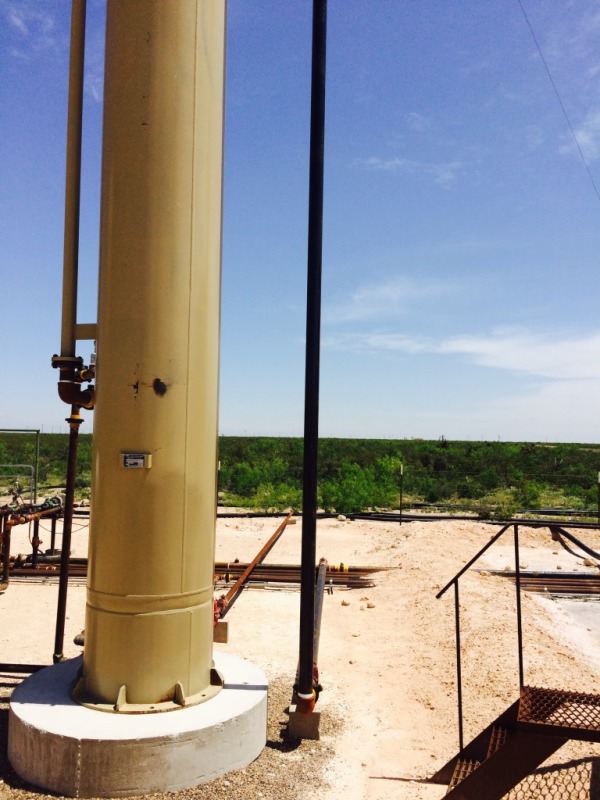
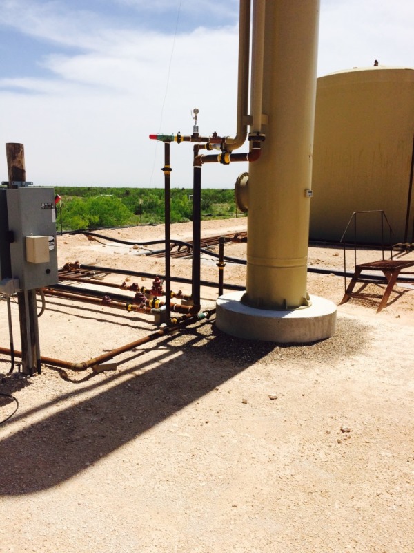
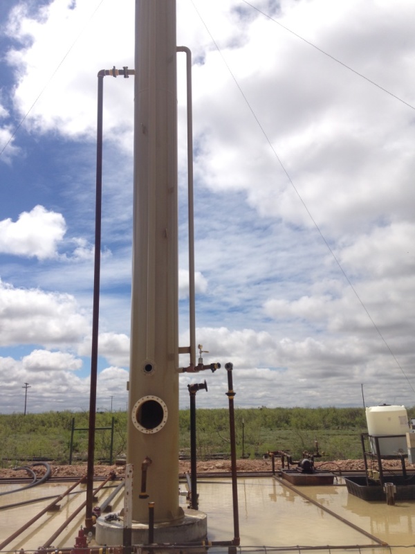
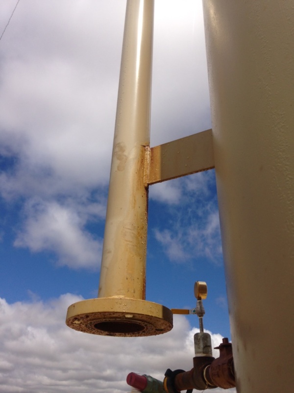
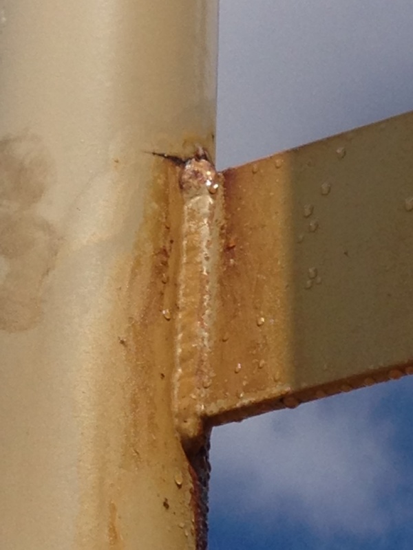
Hello all, I have some equipment as shown in the pictures that have a pipe failure at the support attached.
This is a Vertical Recovery Tower 30" OD X 30' S/S operating at 50 PSI @ 100 F. According to the field foreman, the vessel started leaking 30 min after operation start.
my concerns about this failure were:
1.Transportation and erection procedure, but apparently all pipes are free from any erection load.
2.Material of origin, I checked the MTRs, and the material is according to SA-106,B Smls pipe.
3.Looking at the pictures, there appears to be pipe hanging off of the vessel connections and the pipe is supported by bricks, not concrete foundations. These foundations are probably not offering any support, vertically nor laterally. The pipe seems to be just resting on the bricks. I think it could be a vibration problem, because we cannot see where the pipes go. I suggest the customer should have poured concrete bases for the pipe supports, then secure the pipe with brackets and u-bolts. I think the customer’s pipe is not adequately supported and there must be some type of oscillating load. The failure look like fatigue, normally seen at a compressor station.

I have not be exposed to much to this kind of failures, I would appreciate if someone could guide me to figure out what could be the possible cause of this pipe fracture.
thanks a lot.
 
Replies continue below

Recommended for you

Good morning All,
dhengr,the vessels were hydro as you stated, and they started leaking 30 min after they have been in service, apparently the transportation and erection procedure were good, but really I don't have much information about that, only a few pictures similar to the first one. The only information I have about the pipe is 3" Pipe Sch STD, SA-106,B, the plate support is 1/4" thk, I received a notification from the field foreman announcing that the 2" pipe failed as well at one clip support. Please see file for more details.
 
Dhengr, have you seen this type of crack on similar applications with this kind of supports? The suggestion stated by Littleinch is appropriate to fix this issue, my only concern is the cost of this repair, since as I mentioned before, those are a non code vessels and the customer is cheap on those, for that reason the customer suggest the U-bolt solution as shown in the picture. if you have seen this before could you share how they addressed a repair solution?

Littleinch finally is our responsibility to fix the failure and make sure the vessel work properly, no matter what will be the cost, and your input looks like a really good solution to avoid future problems.

thanks again.
 
There actually is some logic that goes into that kind of detail. And for a lot of low-stress/low-load applications, it will work fine.
I assume the failure mode is differential movement from temperature changes, but that could vary some.
Note that the small-diameter pipe is stiffer with a radial load than a larger pipe would be. So using either a larger pipe or shorter clip (shorter in the vertical direction) would reduce the problem. Turning the flat bar sideways would allow more flexibility. In either case, you're assuming that the stiffness of the pipe and ell are adequate to support the pipe, and just need a standoff at that point.
The main motivations for using that style are corrosion resistance and simplicity, with the corrosion resistance being more critical if the support is submerged.
 
Sergio76:
I’ve seen that kind of crack, on that type of weld detail, on a number of different structures, over the years. That is just an awful weld detail however you cut it, and it will often crack right where it did, under a variety of loading conditions. The stresses at/in that weld toe have the potential of being very high (almost infinite), triaxial stresses; and any imperfection in the weld in that region, which is pretty likely, just amplifies the potential problem. You don’t seem to know what loads or pipe movement you are trying to support/control/restrain, so how are you going to design a fix for the problem? Once the tower is in place, are you trying to prevent too much load on the upper elbows and flanges? You gotta explain to the customer that he went cheap on the first go-round and he can see what he got. You also said he’s got a bunch of these vessels to amortize this engineering effort over. The others will likely need the fix too. Your first photo shows that they weren’t lifting on that 3" pipe, but how can you say the shipping and start of lifting went fine if you can’t answer my questions? I’ll bet most of the damage happened during shipping, a 3" pipe spanning 20-30' will sure bend and vibrate in transit, potentially starting a crack at the toe of that weld. That pipe should be blocked and strapped to the vessel for transit. Maybe with something as simple as a 6"x6" wood block, shaped to fit each part and strapped to the vessel and the pipe. Then, add to the potential transit stressing the operating stresses in the pipe, which will be predominantly tension in the pipe, maybe some bending or axial loading from the pipes below, and the crack would grow and fail, like your picture shows. You also need to know what loads the rest of the piping is applying, to start to make a reasonable analysis. If you do less, you may be quick and cheap, but you are doing a disservice to the client. And, you have to explain this to him, if he really wants a proper fix. I’m really pretty sick and tired of a lot of the quick and dirty, git er done, engineering we see these days. They don’t spend the money or the time to do it right the first time, and then think the fix should be quick and cheap because they think they’ve already paid for it once, even though it didn’t work from the start. Still, if you don’t know the loads and pipe movements, I don’t know how you are really going to provide a good fix. And, if the owner doesn’t want to pay for this effort he’s going to get the same crap he got, on-the-cheap, in the first place.

 
Hello all, after some weeks figuring out about the cause of this failure, it was determined that excess vibration during transportation started this failure, then when the equipment was in operation the additional loads acting on the pipe increase until it fail. I discovered as well that welding quality is poor ( as I mentioned, those are a non code vessels), in order to avoid future problems, we are going to redesign the clip support and our first step is run a stress analysis. the loads I am considering are:
W= pipe weight in direction -Y (assuming Y as vertical axe)
Qz= Wind load in both directions X and Z
P= load at bottom of the flange due to the connection with pipe on field in -Y

is there any other load I may concern, are the constrain points OK?
Wind load happen one at a time, I think Qx is the worse case, is that correct?
is correct also apply the Wind load at the pipe COG?

thanks a lot for your inputs.
 
 http://files.engineering.com/getfile.aspx?folder=9ae8d90d-e7e5-4d7d-990e-2c5d205d7c2e&file=pipe_loads.pdf
Hi Sergio76

I realise I'm late to the party but I'd like to ask a couple of questions:-
1/ how was excess vibration determined during transportation?
2/ What NDT was done on the welds? Because its a non coded vessel it doesn't automatically mean poor welding. For the
future design how will you ensure the welds are good.
3/ What are the additional operating loads you mention? I ask because you need them for the redesign.

I'm not disagreeing that the support could be a lot better designed however I'm not convinced that the failure mode as been correctly identified.
Looking at the photographs there is the joint that failed but it seems to me that there is another joint on the same pipe with exactly the same detail and yet no mention of this as been made, also if excessive vibration set the failure underway what tests have been done to verify there are no cracks in the other joint?
Finally when I look at the failed joint, the crack runs at 90 degrees to the longitudinal direction of the pipe which suggests to me that stresses in the longitudinal direction of the pipe are responsible which may well be caused by differential thermal expansion of the pipe or even during weld cooling in manufacture.
 
Status
Not open for further replies.
Back
Top