Continue to Site

Eng-Tips is the largest engineering community on the Internet

Intelligent Work Forums for Engineering Professionals

  • Congratulations SSS148 on being selected by the Eng-Tips community for having the most helpful posts in the forums last week. Way to Go!

Pipe loop, heater loop 7

Status
Not open for further replies.

Andreas14

Marine/Ocean
Jun 1, 2021
6
Dear expert
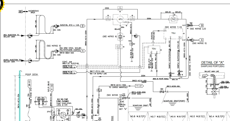
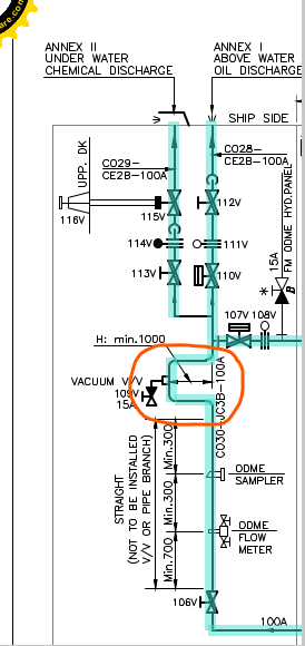
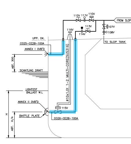
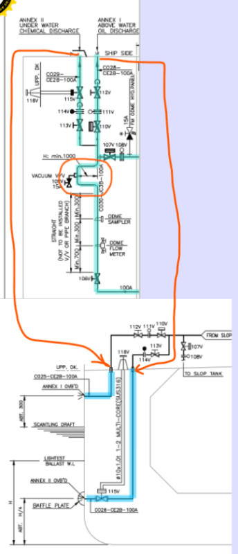
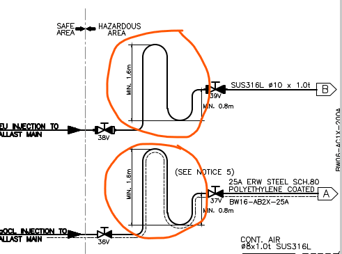
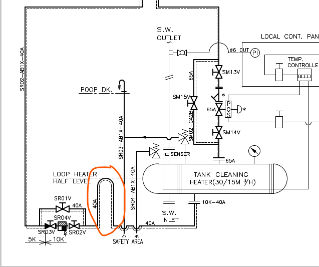
I am just newbie, I would like to know about the purpose of some loop pipe as the below picture show.
Thank you in advance!
image_lnlm6o.png
image_gg4at7.png
 
Replies continue below

Recommended for you

Looks like it might be to keep a minimum liquid level in the tank. You don't give much information, so it is quite difficult to say for sure.

Statements above are the result of works performed solely by my AI providers.
I take no responsibility for any damages or injuries of any kind that may result.
 
What does "Notice 5" say on the first drawing?

For the second drawing I would agree with 1503-44 that it appears to be aimed at preventing the heater tank draining completely. But if that is the case there should be a balancing line from the top of the loop to the top of the tank to prevent siphoning everything out of the tank. It is difficult to draw physical conclusions from a schematic drawing.

Katmar Software - AioFlo Pipe Hydraulics

"An undefined problem has an infinite number of solutions"
 
Right Katmar, great point. They will need to close the valves at exactly the right time to avoid siphon. The gooseneck won't help at all. I dont even see a level indicator (the arrow thing looks like pressure gage) and the "sensor" connects to a temperature controller, so that's a TI ... i guess. (Maybe thats a glass tank? Just kidding.)


Statements above are the result of works performed solely by my AI providers.
I take no responsibility for any damages or injuries of any kind that may result.
 
Impossible to work this out without a decent process description and control philosophy.

Clearly intended to maintain minimum pressures, but the system looks quite odd.

The two on the left look like they want to prevent low pressure blow back from the hazardous area into the safe area and asusming the U bend is full, at worst you have 0.8m head of liquid to push against to get vapour going back the wrong way.

I do like the exit of the pressure relief apparently going to some sort of sprinkler marked "POOP DK". I think I would poop myself if I started to get sprayed by some hot fluid....

And don't get me started on manual bypasses around control valves. [curse]

Remember - More details = better answers
Also: If you get a response it's polite to respond to it.
 
But, but, but ...its . "Only for maintenance purposes" [ponder]

And Whats the 10k and 5k thing about?


If you think I am wrong about anything I say, then please do correct me, but please also refrain from lecturing myself, or others here, in the preschool level details of chem, math and physics. Thank you. I will try to do the same.
 
Thank you very much for your kind support.
I will give you more information about the above question related the first picture. It is the part of ballast water treament system on a ship. And the Note 5 is only about the paint treatment for pipe.
Do you think this kind of loop relate to not only the siphon but also the keeping liquid level?
image_mvjvhp.png
 
There is no other reason that looking at that diagram would suggest.
They appear to all have something to do with an attempt to control liquid levels in that system. Hard to imagine a different function.

If you think I am wrong about anything I say, then please do correct me, but please also refrain from lecturing myself, or others here, in the preschool level details of chem, math and physics. Thank you. I will try to do the same.
 
Doesn't add much more I'm afraid.

Remember - More details = better answers
Also: If you get a response it's polite to respond to it.
 
Those upward loops will act as siphon breaks in either direction as long as the gas pocket is maintained and not flushed out of the pipe. Bleach appears to be one of the fluids, which off-gasses plenty. As long as the pipe diameter in the loop is large compared to the flow rate, it will work as a siphon break without a vent line.

The downward loops are gas seals, the inverse of siphon breaks. The argument for needing a liquid make-up line to preserve the liquid in a gas seal is similar to the argument for needing a vent line to preserve the gas in the siphon breaker.
 
Interesting.

If you think I am wrong about anything I say, then please do correct me, but please also refrain from condescending lectures to myself and others here, in the preschool level details of chem, math and physics. Thank you. I will try to do the same.
 
Dear all experts
I am very glad to have your support buy posting your ideas here. It really help me a lot
By the way, a lot of technical questions I have but it is difficult to find some one who have right knowledge and willing to share it. I would like to make friend with you and I would highly appreciate if you give me any means to contact directly like skype, zalo, or other thing?
Thank you very much.
 
Continue series questions of this subject. I would like to have some explaination for this loop. Thank you.
image_yz1orm.png

image_ljhhuj.png
 
Composite pro - what gas pocket? We know nothing about this system other than it is some sort of water treatment package.

It just looks to me like a glorified Ubend like you get in a sewage system to prevent backflow of gas if the gas is at low pressure (< 1.6m head of liquid)

The diagrams are clearly more of a schematic based around the physical parameters than a classic P&ID, and that's not always a bad thing, but does make it difficult to know sometimes if the pipe is supposed to be vertical or horizontal.

so in the top picture I am assuming the pipe is in fact horizontal as the description says H min 1 m implying Height.

So this is quite definitely a vacuum breaker to prevent syphoning of liquid from one side to the other, whilst maintaining a min 1m head on the other side from flow.

The bottom picture I don't know what the question is - this is simply two different discharge points for the ballast water no?

Remember - More details = better answers
Also: If you get a response it's polite to respond to it.
 
This is a part of cargo oil system in a tanker. The picture showed the discharge line of it. You can see one line come from the slop tank (tank contain dirty oil, the sloop is on this line and one line return the tank.
Thank you for your notice. But I just know respond like picture showed, I think that the way my respond is. Please let me know if I am wrong. Thank you
image_qrbb2d.png

image_rz8kxu.png
 
Andreas,

Sending us little snapshots of what now appear to be two different drawings isn't doing anyone any good here.

I still don't know what your question is, but you seem to have two different drawings of the same thing.

And whilst it might be good for you, direct messaging isn't encouraged on this site, sorry. We're happy to add a little bit of our experience, but we're not a free engineering resource I'm afraid.

Ask questions and post queries, but the ethos of the site is that those questions are there for everyone to learn from, not just the OP.

Remember - More details = better answers
Also: If you get a response it's polite to respond to it.
 
Thank you LittleInch
I understand what you mean. I will make more clear for my question next time. Many difficult question appear on head during working, I do not know that it is here the exactly place to share my questions and knowledge. I do not hope that I could got free engineering resourse here, I just want to meet people who willing to help and share their knowledge. Please let me know if I do some thing wrong in here. Anyhow, thank you so much for your sharing.
 
Status
Not open for further replies.

Part and Inventory Search

Sponsor