Eng-Tips is the largest engineering community on the Internet

Intelligent Work Forums for Engineering Professionals

Pipe shoe thermal displacement/movement - limitations 2

Status
Not open for further replies.

TomoB

Mechanical
Dec 15, 2021
10
0
0
HR
Hello everyone,

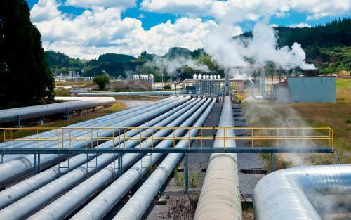
I'm currently working on a piping system of a live steam pipeline (around 500 m long) which serves as a main feed for turbine: DN200, s = 12.5 mm; T = 450°C; p = 68 bar(g).
I am doing a static analysis with ROHR2 software.

I have done numerous analysis for chemical facilities, but mostly on a much smaller scale.
My goal is to design the system with the appropriate number of expansion loops without unnecessarily overdoing it.

I am limited by pipe stress, support loads, thermal displacements and the possibility of fluid hammer, which increases the anchor loads proportionally to the length of the straight pipe section.


1) What would be a reasonable displacement/movement limit for a pipe shoe due to thermal expansion?
Is it limited by support design only and available space on the site?
Are there values from experience or technical literature that I can refer to?

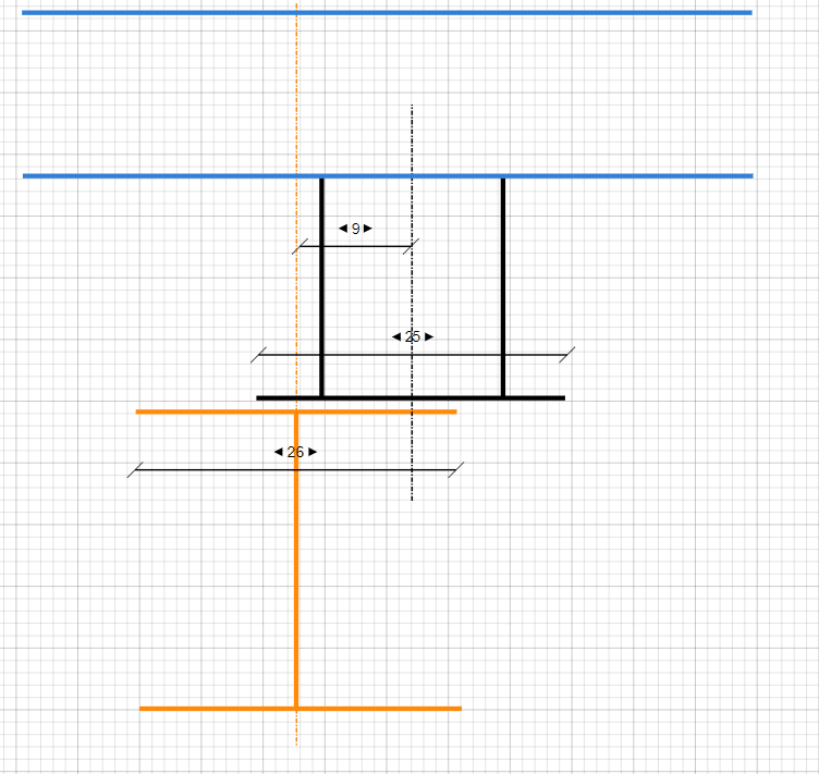
Example: sketch below shows the position of the pipe shoe with 180 mm displacement (from -90 mm to +90 mm position) on a beam.
Pipeshoedisplacement_hezadz.png

From my point of view it would be more economical to adjust the sliding surface to accommodate the movement than to make a loop.

2) Are there any case studies or examples of successful designs for similar piping systems that I can learn from?

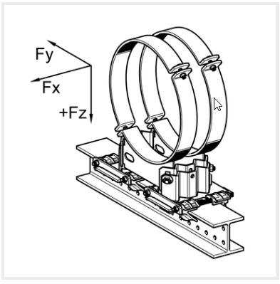
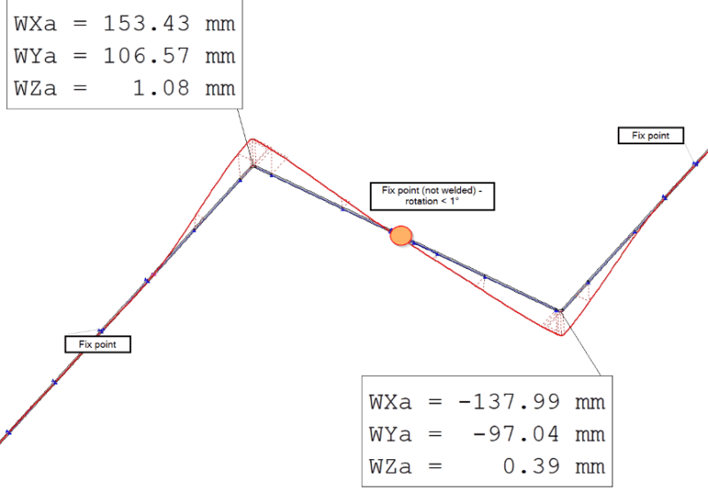
3) In your opinion could a standard fix point - clamped, not welded (not an anchor), serve as a rotating point for a Z-expansion loop according to image below?
Z-loop_Fix_point_r_je372y.png


I'm interested in understanding best practices in minimizing unnecessary expansion loops and having reasonable pipe support loads.

I appreciate any insights, experiences, or references you can share. Thank you in advance!

Best regards,
Tomislav
 
Replies continue below

Recommended for you

We have designed lines with >900mm of movement. Common for geothermal pipelines.

With long runs and large thermal movement a lot of pipe needs to be free to move under thermal expansion. This gives problems with wind and seismic design. The pipe may also squirm and not move where you expect. Always have guide tabs at the limit of thermal movement on the supports.

For your Z loop use a guide + line stop at the point of rotation. You could design a rotating anchor for this.

 
The pipe will tend to rotate about that (not welded) point naturally, without a guide.
If the red line is showing lateral displacement (without that guide), you can see that it isn't moving laterally, so a guide would be redundant. If that analysis is with that guide, remove it and check how much it would deflect laterally. Probably not going to be very much.

Axial deflection is limited by the size of the shoe you are buying. Can be about +/-6", but you should also try to minimize eccentric and torsional loading on WF beams.

--Einstein gave the same test to students every year. When asked why he would do something like that, "Because the answers had changed."
 
I would say do not remove the mid loop guide and line stop just because you can. I have seen a pipe fall off supports when uneven friction (and bit of slope)caused the pipe to ratchet across the support with each thermal cycle, then fall off.
 
With anchors immediately adjacent to the dogleg, it doesn't look like it will be ratcheting very much. In fact that maybe overly restrained, but I can't see the full system. Normally I would but anchors on the ends of the runs, using guides at each ell adjacent to a loop, or dogleg, but guides only if the lateral kickout needs to be limited. Lateral restraint adds bending stress. One guide might be used at the center top of the loop, but that does not often make a convenient point for the structural guys to build an anchor, hence I prefer two guides at the loop's base. If kickout is not too much, then no guides needed.


--Einstein gave the same test to students every year. When asked why he would do something like that, "Because the answers had changed."
 
I think that you need to compromise the eccentricity with the structural engineer on the member sizes and additional torsional capacity. Sometimes you may take torsion at the source by adding member with adequate connection.

I would write a spreadsheet or use the software for adequate displacements on the structure, and use multiples for the number of expansion loops for the total length.

I would not use the welded shoes at those temperatures, I suggest the clamped shoes instead. But you need to think about torsional stability of the clamps in case you use for guiding as well.

 
Hello, thank you all for the advices.
Sorry for not answering, I got sick and had to take some rest. :)

KevinNZ said:
We have designed lines with >900mm of movement. Common for geothermal pipelines.
What was the diameter of the pipelines?

KevinNZ - Thank you for the guide tabs advice, I will use them where necessary.
As for the rotating anchor my question was more related to the design of the anchor itself. Can I use standard pipe shoe, for example Sikla LD HV, acc. to picture below, as a rotational point? The rotation of that point will be less than 1°C. Can I consider the support structure + pipe shoe flexible enough to endure this as a normal load? And if not, how should I design the rotating anchor?
Sikla_LD_HV_d9u504.png

I usually consider pipe shoes that are not welded as a moment/rotation free support. I always consider support rotation up to 1° acceptable, but since for this system everything is on a much bigger scale I wanted to hear your opinions.

1503-44 - I need to have some sort of restraint due to wind load and fluid hammer, otherwise the loads on supports and stress on the pipeline will be too high.
In general, even if it weren't for this loads, I think it is always recommended to control thermal expansion of the system if possible.
 
No. You are thinking oppositely to how a pipe stress engineer should think.
EVERY restraint you add to the system will increase stress.
Start calling yourself a flexibility engineer. That's your real job.
In general you should be thinking towards the objective of keeping stresses as low as possible.
You keep stresses as low as possible by allowing the pipe to expand or contract as freely as possible. What you should be doing is ONLY restraining UNACCEPTABLE movements. Increase the system's flexibility whenever possible and stresses will be reduced.

If you need to put in restraints for wind and earthquake, try to locate as many as possible where there is no or very little thermal movement and combined stress will be kept to a minimum. Of course some restraints you must add to control movements where flexibility cannot be increased and that will add some stress, so your job should only be to minimize the stress caused by those restraints.


--Einstein gave the same test to students every year. When asked why he would do something like that, "Because the answers had changed."
 
Piping design has to be a balance between flexibly required for thermal expansion and restrain required for EQ and wind design. Also too much flexibility can lead to erratic thermal expansion due to uneven friction.

FYI geothermal pipelines can be big (DN1500) and many km long. The location of geothermal recourses means EQ loads are high.

Geothermal-pipes-laying-across-a-large-field_lzrcat.jpg
 
1503-44 Once again thank you for answering, but we are missing the goal of this thread. I already did analysis of the system regarding the locations I have to restrain. I understand what my goals are as a pipe stress engineer. My questions are more related to the execution and feasibility of the calculation model in reality, hence my questions about support design and limitations.
The question was not if mid fix point or other restraints are needed, but can a standard, clamped fix point be used as a rotating anchor (3/6 restraint) as shown on the pictures above?
 
No way.

If the pipe is large, you're going to need some steel clamps, not that tin can wrap.
This is what we use offshore for wind, wave and current loads.

Anchor_Clamp_2_y4o8fi.jpg


--Einstein gave the same test to students every year. When asked why he would do something like that, "Because the answers had changed."
 
A standard, clamped fix point can not be used as a rotating anchor. The pipe needs to rotate. Line stop and guide at the same node with small gaps allows rotation. or you can use a fixed anchor with a pin or joint that allows rotation.
 
Mid point location - I would consider a graphite plate with stops on all 4 sides - allowing a small amount of lateral motion and rotation. The stops are only to ensure none of the slides move enough to risk falling off the supports.

The statement above about not liking slides welded to a high temperature pipe is valid. I did this wrong once, the result was the pipe was sufficiently constrained by the welded connection that thermal stress developing between the hot and cold parts and conditions eventually created a fatigue crack and an exciting leak (40 bar).
 
You cannot weld directly to B31.3/4 pipelines. Hence a full encirclement clamp is preferred. You can weld anything you want to that.

--Einstein gave the same test to students every year. When asked why he would do something like that, "Because the answers had changed."
 
Where does B31.3 say you should not weld supports/fixtures to pipe? I only have access to an other version, but clearly you can weld pipe shoes.

"Integral attachments include plugs, ears, shoes, plates, trunnions, stanchions, structural shapes, and angle clips, cast on or welded to
the piping"
 
Sorry. B31.4 & 8

--Einstein gave the same test to students every year. When asked why he would do something like that, "Because the answers had changed."
 
Status
Not open for further replies.
Back
Top