Eng-Tips is the largest engineering community on the Internet

Intelligent Work Forums for Engineering Professionals

Pipe sizing for Spray Nozzles 3

Status
Not open for further replies.

msii

Mechanical
Nov 1, 2017
44
0
0
AU
Hi All,

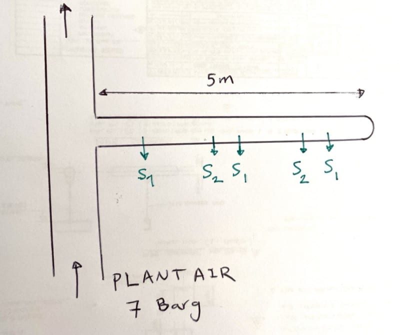
I'm designing a compressed air system that gets a connection from a Plant Air compressed system at 7 barG. I want to size the connecting piping in the way that it can provide enough flow and pressure to the all spray nozzles in attached. There are two types of nozzles (S1 and S2) need to be installed on the line. The line is approximately 5 meters long. S1 can flow 120 Nm3/hr and S2 can flow 50 Nm3/hr at 7 Barg.
I'm looking to find the related formula and calculations I need to do to ensure the pipe size is enough and I et enough flow and pressure at the last nozzle.

Image_qqgquv.jpg

Thanks for your guidelines.

Please let me know what formulation and guidebook I can follow to resolve this for compressible fluid.
 
Replies continue below

Recommended for you

It would be possible to make this a very complicated calculation, taking the changes in flowrate along the length of the pipe (as some air exits through the nozzles) into account and optimizing the diameter of the pipe for each segment between the nozzles. There could also be a debate on whether it would be more accurate to assume isothermal or adiabatic compressible flow.

However, in this particular situation all of that is irrelevant and it is a very simple design that is driven more by economics than by hydraulics or thermodynamics.

No matter what you do, there will be a lower pressure at the end of the branch than where it joins the header and the first decision is what limit you need to impose on this pressure drop. It doesn't have to be cast in stone - you can come back and test how this decision impacts the design later.

To make the calculations easier we can assume that the full flowrate applies to the whole length of the pipe. If it turns out that this requires the pipe to be large and expensive we can go into more detail later.

As a starting point I would suggest that the pressure drop be limited to 5% of the inlet pressure (in absolute terms) as this would limit the change in air density along the pipe and if all the nozzles "see" air with pressures and densities within 5% of each other the flow through the nozzles is likley to be sufficiently similar.

I prefer to use mass based flowrates and I converted your values to a total of 590 kg/h. Assuming isothermal compressible flow and taking the density as 9.4 kg/m3 and the viscosity as 0.018 cP for air at 8 bara and 25 C, and using a pressure drop of 0.4 bar over a 5 m length the required diameter pipe is 23.6 mm. Switching the assumption to incompressible flow would make this 23.4 mm and the adiabatic case would be somewhere between those two limits.

The velocity in the pipe would be about 40 m/s which is a bit high and depending on the noise requirements you may want to use a lower velocity - but the nozzles are likely to be noisy anyway. If this were my decision I would select a 40 mm pipe to make it self supporting and easy to fabricate. The pressure drop varies with the 5th power of the pipe diameter so using a Sch40 1" pipe would make the pressure drop 0.2 bar and a 1.5" pipe would be about 0.02 bar.

So overall, a simple design.

Katmar Software - AioFlo Pipe Hydraulics

"An undefined problem has an infinite number of solutions"
 
Suggest nothing less than 2", or 2.5" diameter.
A sch 40, or even XXS to provide mechanical strength and limit vibration, reduce velocity and potential erosion.
Cheap insurance.

--Einstein gave the same test to students every year. When asked why he would do something like that, "Because the answers had changed."
 
The other "sniff test" you can do to check the above calculations is to calculate if you have it, the area of the nozzles / branches, sum them up and then make sure that the header pipe square area is at least as big as the sum of the area of the branches. More than one will give you lower difference in pressure along the header, but it's a good initial start point to get more or less equal pressure at the different branches.

That seems quite a lot of air you're "distributing" in a 5m length of pipe. I've never heard of air nozzles being referred to as "spraying" air. Is there something else being added to become a spray?

You need to know how sensitive your system is to variations in air pressure. Katmars 5% drop is quite a good number to use for initial sizing purposes, but that's up to you.

Remember - More details = better answers
Also: If you get a response it's polite to respond to it.
 
There's no formula per se for this specific situation; it's just basic fluid flow. The key to even distribution across all nozzles is to ensure that the pressure drop across the distribution manifold is much much less than the pressure drop across the nozzles. That's the key to even distribution across all nozzles. Only way to ensure this is to build a hydraulic model of the system to check those dP's. This is super easy if you have access to a simulator; if not, you can certainly still do it with Excel spreadsheet, just takes longer.

 
Status
Not open for further replies.
Back
Top