Continue to Site

Eng-Tips is the largest engineering community on the Internet

Intelligent Work Forums for Engineering Professionals

  • Congratulations KootK on being selected by the Eng-Tips community for having the most helpful posts in the forums last week. Way to Go!

Pipe support corssing creek and rail ways 2

Status
Not open for further replies.

GBMRAO

Structural
Sep 4, 2018
31
Hi, Structural tech friends,

I have a client who is asking me to design support for a 36" diameter water pipe crossing two creeks and a railway crossing. For the railway crossing, i am just maintaining the bridge heights and column spacing so that i don't have any issues.

for the pipe support, they want continuous pipe support. I was thinking of concrete piers at either end with a concrete beam. the concrete beam will have a semi-circle concave to sit the pipe. This is my idea.

Can anyone suggest any guidelines for Ductile Iron pipe support examples or suggestions? its 108 ft long and 85 ft long segments. They only can have end supports.
i am new to this pipe supports. i can design column and beam to support the weight and dynamic movements, wind and earthquake loads. but could not find good online examples on continuous supports.

Any help is appreciated.

 
Replies continue below

Recommended for you

This should be helpful: Design of Ductile Iron Pipe on Supports

See correct link in my post below.

 
Also, do some googling. Lots of PWDs have typical aerial pipe crossing details. They'll give you a good idea of some ways of approaching it.
 
phameng - that link goes to your C drive....

Be aware Ductile iron pipe often has push fit or external connections so a flat beam needs to allow for these.

Whilst DI is generally quite good for corrosion, semi circle or depressions in a beam give you no end of issues wrt corrosion under the pipe at the pipe/beam interface.

Continuous pipe support as you describe is quite unusual. Why do they need it? There's a good reason why you can't find any examples.

85 feet as a single pipe?? Are you sure?

Remember - More details = better answers
Also: If you get a response it's polite to respond to it.
 
run your ductile through a steel casing
provide full mechanical joint restraint
provide drain holes?
 
Thirty six inch pipe can span pretty far on its own. If you can strategically place supports at 40 feet or so, you might have a crossing. As LittleInch said, you'll need flanged connections for the entire crossing and for some distance beyond. Now 85 feet is a lot.
In South Florida, these are very common. Going under canals is a pain due to groundwater. So they span over the canals. Now the canals aren't subject to uncontrolled scour (the flow is controlled), so you can drive piles right into the bottom. And I can't say I've seen any 85 foot spans, either.
[li]Make sure you're well over high water.[/li]
[li]Be sure to place fan shaped barriers at the ends to keep youths from trying to cross on foot.[/li]

 
The Dipra sheet phamENG posted has some useful components to it but will only get you so far. Take a look at Figure 1, this is how you want to support the pipe.... Either side of the bell fitting. Not a continuous support.

If you want the pipe to span itself as a bridge, take a look at the following: Link With that being said, you are not going to get 108ft span from the pipe by itself.

Does this pipe crossing have to have a deck? Will it need FRP grating? Will there be any Air Relief Valves located along the length? If this were my project I would design 2 girders (Steel or Prestressed Concrete) with a saddle diaphragm in the middle. I have a current pipe crossing bridge currently in construction using 142 ft long spliced post tensioned girders. If there is no deck then you will need your diaphragm to be close to full height. If you have a deck, you can probably get away with a shorter diaphragm and mount the pipe either above or below the diaphragm.

Take a look at the attached pipe crossing for a bridge that I designed. Saddle diaphragms. Note that you will need to account for the rotation at the ends of the bridge. Those bell fittings only allow a certain amount of rotation. Depending on the flexibility of the superstructure, check the rotation and make sure you don't exceed the allowable rotation tolerance of those fittings. We used 2 fittings back to back to account for the extra rotation.


 https://files.engineering.com/getfile.aspx?folder=3f83dd34-3cdd-44ee-82d9-d014d73148df&file=Pipe_Crossing.png
Maybe double an arch steel truss bridge, with the pipe lay on the platform, when crossing the creeks.
 
Our office has done several where we do provide continuous support to the utility line the entire span of the bridge but I'm curious on whether or not that is really necessary for your project. It's going to involve a lot more concrete and increase the weight significantly. Will involve using modified wide flange prestressed girders and lots of CIP concrete.
 
... its 108 ft long and 85 ft long segments. They only can have end supports.

Why this requirement?
 
r13 said:
Why this requirement?

In bridge design over a waterway, hydraulics and environmental concerns will always trump the structural design. The structural engineer needs to tailor the structure to satisfy both of these requirements. Even if it's not necessary to keep the piers out of the design flood elevation most often it is just faster and cheaper to just do so to avoid running the hydraulic analysis and getting the environmental permits. Once you start putting foundations inside the flood elevation... you open a can of worms.
 
What exactly do they mean with "continuous support" ?
Would supports every 48" (or whatever fits the bill) work, as opposed to treating the pipe as a beam on 2 end supports?

I would'nt be surprised as whoever wrote the tech specs, doesn't know the difference between these three distinct situations.
 
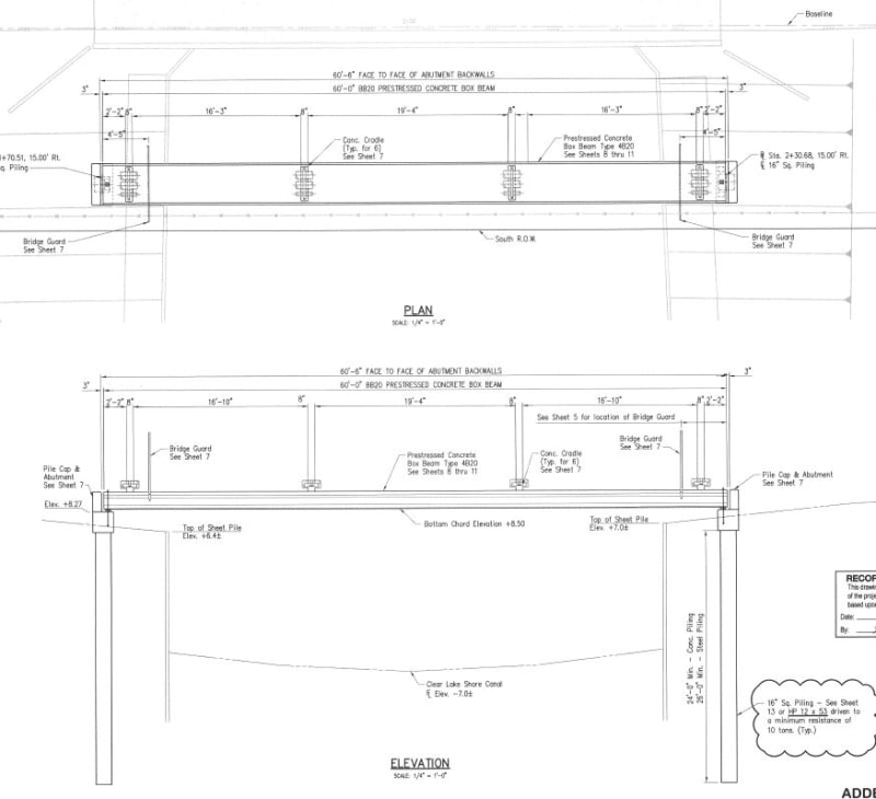
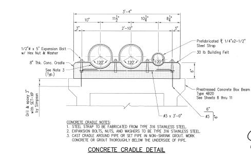
36" is a larger pipe, but engineers in my office have used a single pre-stressed bridge box beam girder to span creeks etc. Then, they have built a series of pipe cradles across the top of the girder at whatever spacing the pipe engineer wants.

Here's one with smaller pipes.

Capture_v8jzho.jpg


Capture_blwq7e.jpg
 
Status
Not open for further replies.

Part and Inventory Search

Sponsor