Continue to Site

Eng-Tips is the largest engineering community on the Internet

Intelligent Work Forums for Engineering Professionals

  • Congratulations IDS on being selected by the Eng-Tips community for having the most helpful posts in the forums last week. Way to Go!

Pipe support with round bars

Status
Not open for further replies.

DBreyer

Materials
May 16, 2014
62
Hi all,

I am currently looking at an older pipe which is thinning due to internal corrosion.
The pipe rests on concrete sleepers with a round steel bar on top (to minimise corrosion at the support location). There is no reinforcement on the pipe itself.

Now to my Question:
Is there a good and practicable way to calculate the stress in the pipe at the support location?
I would assume there are high local stresses due to the "theoretical" point contact (the pipe will probably yield a bit in reality). As the pipe is getting thinner I am worried about a failure of the line due to the high stresses.

For pipe resting on a flat bar I would calculate the stresses according to Roark's Formulas for Stress and Strain Table 13.3 Equation 8b (Center load on a very short length).
I could assume that the Diameter of the round bar is equal the width of a flat but I am worried that the results would be non-conservative.
Do you know of a way to calculate the resulting stresses short of doing FEA? How would you set the limits?

Thank you for your help.

Kind regards
Daniel

 
Replies continue below

Recommended for you

I've seen it done by the piping guys based on something similiar to what you describe and they used a factored yield stress at the point of contact.

You might like to look at something like this
Remember - More details = better answers
Also: If you get a response it's polite to respond to it.
 

I will suggest you to look AWWA M 11 Steel Pipe A Guide for Design and Installation ; SADDLE SUPPORTS .

Some interesting points;

- The maximum fiber stress occurs at supports when the pipe half-filled condition due to pipe section becomes out of round,
- Regarding the stress ; copy and paste from the same ref.(.... For equal load, the stresses are less for a large contact angle than for a small one, and interestingly, their intensity is practically independent of the width of the saddle.)
 
@1503-44: thank you for the reference. did you have a particular module in mind? When follwoing the link I always end with the "ASME B31G Pipe Corrosion Defect Calculation Module"

@HTURKAK: Unfortunately the line is not sitting in a saddle but rather on a round steel bar. So it would be a saddle with 0° angle. I am not sure that this is within the applicable Limits of the equation.
 
Yes it is the ASME B31G Pipe Corrosion Defect Calculation Module that I had in mind. Hoop stress will be your primary mode of failure in pressurized pipe, so I'd concentrate on that. Contact stresses should be relatively low, unless you have very long pipe spans, in which case the longitudinal bending stress would also be high. High contact stress usually only occurs after you have made the pipe spans so long that pipe center span deflections have already become a major problem. I think you'd have to have very short spans with very heavily loaded pipe, something in addition to the weight that it can hold inside, in order for contact stress to become a problem. Or maybe paper thin pipe?


I agree with you but , IMO ,the proposed method in AWWA M 11 could be used with an assumption of a saddle with small degree. My concern for the use of Roark's Formulas for Stress and Strain Table 13.3 Equation 8b is, the equation does not account internal pressure and longitudinal stresses. The subject formula could be used for (Cylindrical shells with closed ends and with end supports loaded at span ). Or, let me ask ; how you are planning to contribute the effect of hoop stresses and bending stresses ?

I will propose you, do your calculation with Roark's Formula and provide some data ( dia, thickness, support reaction, internal pressure , hoop stress and bending stress ) . I will perform a hand calc. then we may compare ..
 
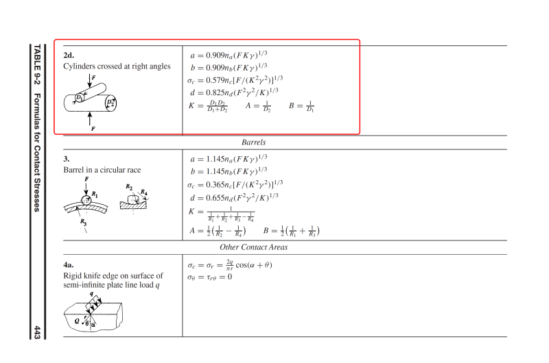
looks like this
Formulas_for_Stress_Strain_n_Structural_matrices_Pilkey_2005_1_vud25i.png

Formulas_for_Stress_Strain_n_Structural_matrices_Pilkey_2005_2_qhsbha.png
 

Dear robyengIT , the formulas at TABLE 9-2 for contact stresses..and case 2d is for solid Cylinders crossed at right angles.

The thread is for the stresses developing at pipe resting on a flat bar. The stresses for this case largely depends on dia, wall thk, internal pressure , wt of content and developing support reaction and contact angle ...
 
Hturkak.

Read to read the OP more closely.

Says "round steel bar..."

Looks good to me.

Remember - More details = better answers
Also: If you get a response it's polite to respond to it.
 
Dear LittleInch (Petroleum) , Dear robyengIT (Mechanical)

The thread is for the stresses developing at pipe resting on a round bar. ( I made a mistake with writing flat bar in previous comment )

The formula suggested in (Walter D. Pilkey - Formulas for Stress, Strain, and Structural Matrices ) at TABLE 9-2 case 2d for contact stresses..

- The calculated stresses are contact stresses (HERTZIAN ) between two SOLID CYLINDERS crossed at right angles . The support , in this case round bar solid but the pipe is hollow cylinder..

- If the pipe is small dia with heavy wall thk (say XXS ) the assumption of solid cylinder could be acceptable. However, the calculated contact stress does not give an opinion for the max. stress allowable for the pipe at support. ( the local bending stress at support and longitudinal bending stress due to beam action shall be calculated to see the case)

Still i will suggest to look AWWA M 11 Steel Pipe A Guide for Design and Installation ; Chapter 7.


Status
Not open for further replies.

Part and Inventory Search

Sponsor