Eng-Tips is the largest engineering community on the Internet

Intelligent Work Forums for Engineering Professionals

PIPELINE PROBLEM 3

Status
Not open for further replies.

Mncedisi Nzipo

Mechanical
Jul 26, 2017
7
0
0
ZA
disel_pump_-_Copy_wt7uno.png

Hi,
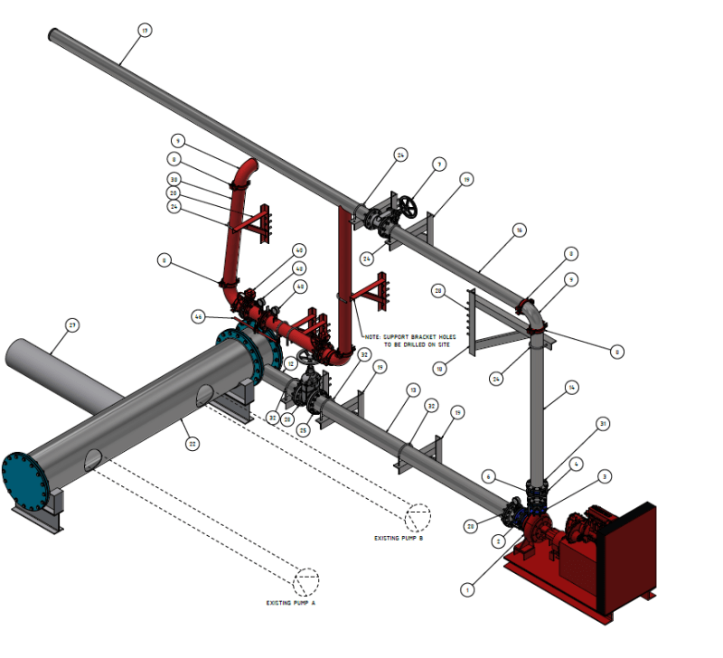
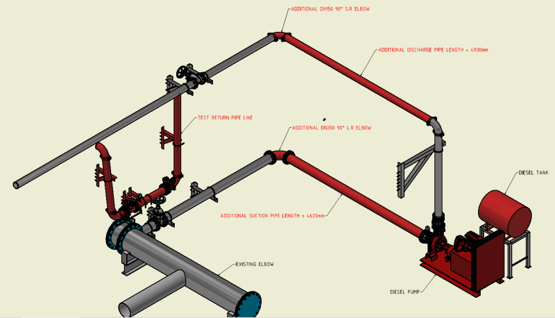
I am currectly designing a pipeline for a diesel powered fire pump and we are having some technicalities with the client.
The initital design had a straight suction which was perfect for the application.
However the client was denied permission to extent their boundary fence. Hence we are now forced to have a bend on the suction line.
My questions is how best can we put a dn200 90 degree elbow on the suction line without causing much harm to the pump.
 
Replies continue below

Recommended for you

Try to keep it a minimum of 2m (10 diameters) away from the pump flange. Use straight pipe between the bend and pump flange.

--Einstein gave the same test to students every year. When asked why he would do something like that, "Because the answers had changed."
 
Got a sketch or picture so we can see what you're talking about?

Suction from what?

Pressures? flow rates, velocities all make a difference as to what is acceptable and what isn't / any issues.

But yes, max distance from the bend if you can or make it DN 300?


Remember - More details = better answers
Also: If you get a response it's polite to respond to it.
 
Thank you for your help.
Please note that i have added a sketch on the origional post.
To answer a your questions
1. The suction line is connected to an already existing manifold that is used by the client.
 
Nothing wrong with that layout at all.

If you really really want to do something then you could stick in a flow straightener in that inlet/suction leg, but >20D of straight pipe should be good enough to avoid any swirl.

Remember - More details = better answers
Also: If you get a response it's polite to respond to it.
 
Almost 5m is fine. A lot more than needed. You look good.

--Einstein gave the same test to students every year. When asked why he would do something like that, "Because the answers had changed."
 
Whatever problems you may have, they won't be because of the inlet line bend.

Remember - More details = better answers
Also: If you get a response it's polite to respond to it.
 
What is the nominal diameter of the suction piping and what is inlet diameter of the centrifugal pump suction.??

Usually the suction piping is one size larger and there is a flat-side-up eccentric reducer at the pump..

But you have not given us enough information .... Where is your PID ?... Where is your pump datasheet/catalog cut ?


Do you have an isolation valve and check valve on the pump discharge ?..... Who knows...
....This is your very first piping layout, Isn't it ?

We can see everything but this on your CD cad model

MJCronin
Sr. Process Engineer
 
Come on MJC, put your glasses on.

Its an 8" inlet and 6" outlet.
The reducer I can't see fair enough.
Looks like a NRV on the outlet and the isolation valve is a bit further down the system.

Think you're just being a bit grumpy today....

Remember - More details = better answers
Also: If you get a response it's polite to respond to it.
 
disel_pump_1_bic0wq.png

@MJCronin
Please note that i decided to share an isometric view because i find it easier to comprehend and explain sice its a picture.
The suction pipe is dn200 and the pump inlet is dn150 and there is an eccentirc reducer connected to an expansion joint that is connecte to the pump flange.
I have attached another isometric drawing of the initial design before we faced some technicalities with the client.
Everything was calculated and approved. There is a non return valve and a gate valve on the discharge pipeline.
 
@Mncedisi Nzipo
Which standard did you implement: CEN/TR 13932, ANSI/HI 9.6+9.8, API 686? Note than most companies in oil&gas industry use API&ANSI/HI.

Exxon Mobil said:
GP 03-03-02
1.2. HI – Hydraulic Institute
Standards of the Hydraulic Institute should be used as stated in this GP.

IP 3-3-2
2.1 Table 1 lists the standards which shall be used with this practice.
TABLE 1
STANDARDS
HI Standard
Hydraulic Institute Standards

Shell's std. DEP 31.29.00.10 said:
1.1 …
This DEP is based on API RP 686 …; Part III of this DEP amends, supplements and deletes various clauses of API RP 686. All clauses of API RP 686 not modified by this DEP remain valid as written.

Samsung's std. SEM-3074 said:
1.2 Relevant Manuals and Standards

(4) API 686 "Recommended Practice for Machinery Installation and Installation Design"

JGC's std. JGS 210-120-1-27 said:
5. RELATED DOCUMENTS
The following publications will constitute a part of this standard practice. Unless otherwise specified, refer to the latest edition. Applicable publications for the Project will be specified in each of the Pro-ject Specifications.

Hydraulic Institute
Hydraulic Institute Standards

image.png
image.png
 
Status
Not open for further replies.
Back
Top