grunt58
Mechanical
- Feb 4, 2005
- 490
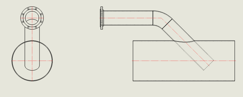
Piping Iso diagrams are from the center of the pipe, correct? See attached sample.
Follow along with the video below to see how to install our site as a web app on your home screen.
Note: This feature may not be available in some browsers.