Continue to Site

Eng-Tips is the largest engineering community on the Internet

Intelligent Work Forums for Engineering Professionals

  • Congratulations pierreick on being selected by the Eng-Tips community for having the most helpful posts in the forums last week. Way to Go!

Piston ring to cylinder wall pressure 5

Status
Not open for further replies.

JerinG

Mechanical
Oct 18, 2009
99
Can someone tell me what are usual numbers for pressures in MPa for piston rings in nowadays gasoline engines? With pressure I mean contact pressure between piston ring and cylinder wall.
 
Replies continue below

Recommended for you

Static tension only part of the story. Gas pressure behind the ring dominates at high loads. As a first approximation you could use combustion pressure (say 100 bar - 10 MPa) as a proxy for peak contact pressure on the cylinder. Clearly this will fluctuate significantly during the cycle.

je suis charlie
 
A precise value answering your question is not possible.

Modern oil ring packages might be designed to 100 psi or .7 MPa using the formula, unit pressure = 2 x tangential load ( lbs) / (bore diameter x rail width totals (in inches)) for modern automotive engines. This is much reduced from pressures used 40 years ago.

Compression rings are perhaps 5 - 15% of that (each).

Handbook values are usually estimated using the full ring axial width. However, the actual contact width is not that wide on a normal ring. This is because of the convex surface or taper angle on the O.D. face of the ring. Because the contact area of a normal ring might be closer to half the total ring width, you might double the handbook values to get a better estimate.

As noted by Gruntguru, the gas pressure behind the compression rings adds considerably to the loading of those rings during some parts of the cycle.
 
And to make it more fun there should be no contact between them and the cylinder wall. Or is this a test?
There are a lot of variables involved.
 
Thanks for answers. I know that there is a lot to cover here, but I'm running a project of a new type of combustion engine on a shoestring budget [thumbsup2]. Our team put the prototype together (not just in CAD but a real life engine prototype) and everything is ready for start, we just need to solve some issues with sealing the combustion chambers to get enough compression for first start.

Here is one screenshot of so called "piston", which is not really a piston [shadeshappy]:
2019_11_15-13_38_15_qelwon.png


Before you attack me with why am I calling mine seals piston rings in reality I don't. I just want to use some experiences that are known for piston rings that I can use in development of mine u-type combustion chamber seals (short: U-seals). [blush]

I was asking for ring pressure, because of spring force selection. As you can see, we have a few coil springs around the "piston" (under violet colored elements) and they have a function of producing enough force so that we can achive proper sealing.

If anyone can give me some info about proper literature about this part of engine development, I will be very grateful.
 
University courses and student theses provide useful information about detailed design considerations. A Google search for piston rings on .edu domains with file type pdf yields what appear to be useful resources. Since your seals aren't rings per se, you may also find useful results searching for Wankel seal design with file type pdf. You don't have to read very many papers before realizing that piston seals look quite simple, but their design is quite complex. Rings are well understood and quite a bit simpler than the seals you plan; the top compression ring is the most critical, and its comprised of a single piece of iron or steel that is self tensioning with the entire ring moving at the same velocity. In contrast, your seals (and those of the Wankel) are multi-segment, require sealing across segment boundaries, are spring loaded, and have a non-uniform velocity profile. In short, your seals are going to be very difficult to get right, especially if you plan to prototype them to perfection rather than simulate/test/refine and repeat as is common.

P.S. Have you seen the Butterfly Engine? It uses a "piston" that looks similar to yours.
 
Great and thanks for help RodRico. I will check the details.

As it goes for middle seal, it is already made and tested. Our piston didn't have very well designed side U-seals (green color) and side seal (red color). I had to get the exact geometry of my piston bore and now I'm designing from bottom.

Middle seal does not move and seal in segments. It has an amplitude of 30° left and right and it is always pressed on constant radius. It is spring loaded with coil springs from top (both seals are - top and bottom) and from both sides. Now it is designed that it will work together with red side seal and togehter they will provide good sealing with no gaps. Of course some blowby is always present.

I'm an engineer that joined the project about two and a half years ago and some of these parts were already designed and manufactured. In these two and half years I detailed a lot of parts on the engine and finished the design. After that, everything had to be manufactured. And we are very close to something. But as you said, sometimes trial and error is the only way to go. Especially if there is not a lot of budget behind.
 
Two more questions for practical enginners.

Does enybody know how long does a cylinder at TDC maintain compression to certain % of maximum? I'm talking about a compression cycle with piston stopped at TDC with no ignition and then measuring pressure drop in certain amount of time.

Second one: If I have a comperssion ratio (CR) of 10,3:1 then the pressure according to isothermal process is:
Vd = 550 cm3 - I have total displacement of 2200 cm3 so one chamber is 550 cm3.
CR = (Vd+Vc)/Vc, where Vc is compressed volume.
I get that Vc is 59 cm3.
I have no turbine on the intake, so pressure in the start of compression is 1 bar and according to isothemral process I get pressure in the end of process 9,3 bar.
If I assume polytropic process with inex n = 1,4, then I get pressure at TDC about 23 bar.
So which is realistic in reality and how much is usually lost in modern petrol engines?


I've never seen a figure for how much compression pressure the seals must hold over a given time. First, every reference I've seen relates to blow-by after combustion rather than blow-by during compression. Second, seals operate very differently under dynamic conditions than static conditions, so I'm not sure of the value of a static requirement. Third, the objective is to reduce blow by as much as possible during dynamic operation while keeping friction low, two opposing requirements that must be balanced. In other words, it's one the engineering trades associated with engine design.

Compression isn't a constant temperature process, so it's not isothermal. It approximates an isentropic (constant entropy or reversible adiabatic) process. In the isentropic calculation P2 = P1 * (V1/V2)^y , V1/V2 is compression ratio, and y typically ranges from 1.3 to 1.4 (the lower figure during expansion and the higher during compression). In your case, P2 = 100,000 * 10.3^1.4 yields an approximate pressure at the end of compression equal to 2,618,015 Pa or 26 bar. The hard limit on total compression ratio (including boost if any) in a typical spark ignition engine is a function of temperature (intake temperature, intercooler drop, etc) and ignition delay (which is determined primarily by fuel octane). 10.3:1 is realistic (if a little low for a modern engine).
 
I would recommend you start by researching cylinder leakdown tests, they're a common means of checking blowby in a cold engine.
 
Thanks CWB1... Learn something new every day!

I found an article on the HotRod Network that describes the procedure for a leak down test concluding "even for normally aspirated engines, respectable leakage numbers would be anywhere from 8 to 12 percent with a variation between cylinders of 4 to 5 percent."
 
Thanks for answer. I will check it out.

As it goes for compression pressure, I got some info that an engine (in this case it was BMW boxer R1150) with CR of 10,3 should have maximum compression at TDC of about 8-10 bar.
BMW R1150 compression test
So with all the losses that's closer to isothermal 9 bar than 25 bar according to theoretical isentropic process. That means that isentropic calculation is far away from reality, or am I missing something here?
 
LOL! I don't recommend checking engine design math using amateur forums where users say things like "Thanks for the translation of bar to psi. This is the information that i needed." Instead, I suggest you use college course materials (see AME436 pg 5 below or visit the University of Colorado's Model of Basic Otto Cycle), or if you're lazy, you can even use Wikipedia (see Compression Ratio, Relationship with the pressure ratio) for some of the basics.

Otto_gqiddc.jpg
 
Sorry RodRico for my lack of correctness, but that was only posted for practical reasons. I also talked with mechanics and usuall good results of compression tests for mentioned engine are around 10 bar.

I will most sure check your links and do the best I can with them. But in the end when it comes to compression tests and the pressures in reality are more then half less of what they were in calculated values, then you start thinking.
 
JerinG, Welcome to engine design where ideal calculations alone aren't sufficient. That doesn't mean, however, that we should use the wrong calculation just because it seems closer to empirical results!

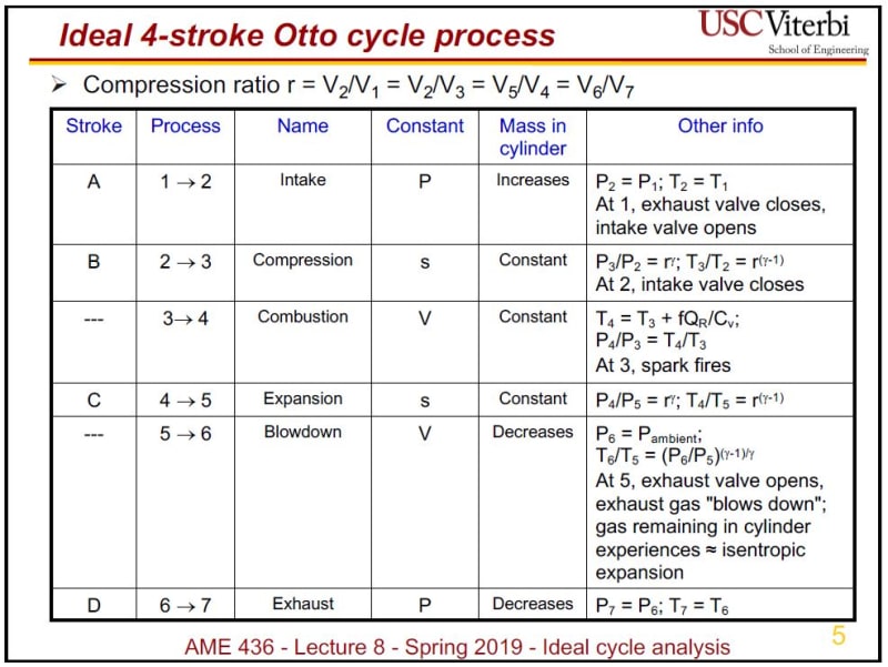
The theoretical isentropic calculations don't include port flow (volumetric efficiency), impacts of valve timing, heat transfer, or compression leakage (aka dynamic compression effects). Once properly adjusted for these factors, I assure you it would match your empirical expectation (assuming those expectations are correct... see "by the way" below). It is a dangerous design error to use an isothermal (constant temperature) calculation as gasses under compression do in fact increase in temperature (otherwise a diesel wouldn't work). Your isothermal calculation only appears correct because its errors are (apparently) roughly equal to the losses that aren't accounted for in the theoretical isentropic calculation. That's merely a coincidence. Read the references I provided.

By the way, this article shows the BMW R1100GS also has a 10.3:1 compression ratio, and this video of an R1100GS compression test shows 200 psi (13.8 bar). That's 40% higher than your expectation.

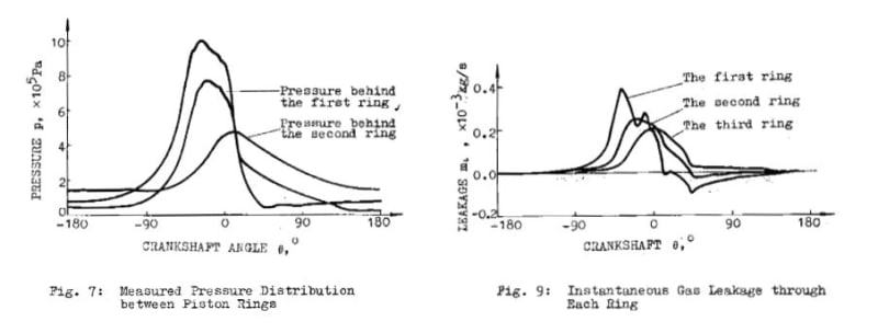
P.S. We don't actually use the isentropic calculations for engine modelling; they're used for approximations. Instead, we use PV=mRT where P is in Pascals, V is in cubic meters, m is air mass in kilograms, R (the specific gas constant) is 287, and T is in Kelvin. We break each cycle into very fine time steps and keep track of mass transfer, heat transfer, and volume then calculate pressure. The mass calculation does use a typical value for lost mass during compression and expansion that no doubt approximates the 8% to 12% loss of compression pressure (I plan to check this just to satisfy my curiosity).
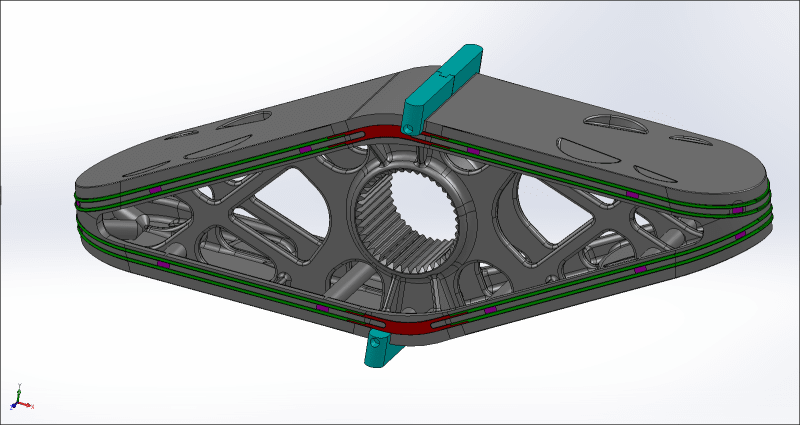
 
Intake valve closes some significant number of crank degrees after BDC, which reduces effective compression ratio at cranking speed. (It will push some of the charge back out again until the valve actually closes.) At cranking speed, heat loss to the surroundings will be significant, which reduces the temperature and pressure after the compression stroke.
 
I went through my reference library of pdfs and found "Prediction for the Sealing Characteristics of Piston Rings of a Reciprocating Compressor." The paper provides a means for calculating pressure and mass leakage through each ring of a three ring piston and compares results of those calculations to data measured using a specialized rig. Keep in mind the paper's calculations and results relate to circular pistons and seals.

Capture_f1hsif.jpg
 
Hey, RodRico, thanks for all your effort in searching around the literature. In my defense, I'm not an engine design engineer, but as I said before, about two years ago one person came around asking me for help with getting his project through what should be "final" stages of design. [upsidedown] We had to do a lot of work and beause of lack of funding some parts of the engine were "untouchable". Now in the end I'm trying to correct chamber sealing and design for which they optimisticly thought it will work.

You must understand that when the latest chamber sealing design will be installed in the engine, I will somehow have to test it with limited resources. All I have is a cheap compression tester and that's why I'm asking about what kind of pressures can I expect. I try to get as much info as I can and then filter it down to what I need and what will help me to do the job.

And I'm far away from using wrong physical laws on purpouse, because reality is different, but such differences makes you think, as I mentioned. Without proper measuring equipment and funds it is very hard to do anything good enough and some trial and error is needed. But we are engineers and I will get through this because we are too close to finish now. Again thanks for help and if anyone has anything to add, they are most welcome.

I saw your link on Butterfly engine (I think you edited the post and I missed it before). I must admit I haven't seen it yet and it looks interesting, but somewhat more complex design as ours.
 
One more question here. We are talking a lot about pressure before ignition and I will be very happy if I get to 10 bar from what I'm reading here. But every engine probably has some tolerances here. Of course we want to get as high as possible without knocking for petrol engines. But what is the lower limit of pressure at the end of compression phase for some value of CR, so that the engine is still able to run in some decent parameters?
 
Status
Not open for further replies.

Part and Inventory Search

Sponsor