I was hoping to get away with asking a basic filter question - but that isn't going to happen.
")
Here is more info.
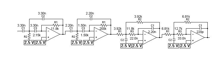
I based the design of the filter on this equation.
Knock Frequency (in kHz) = 1800 / (pi * d) where d = piston diameter
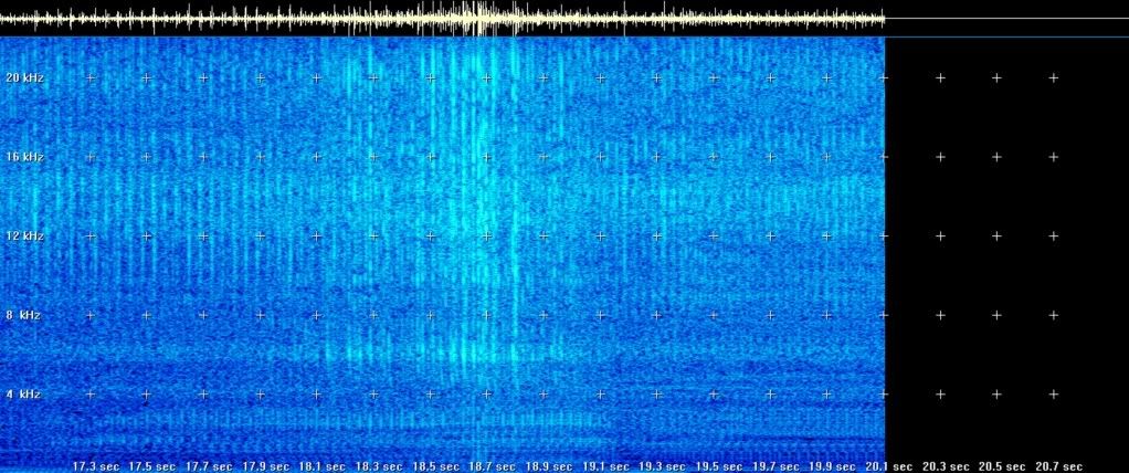
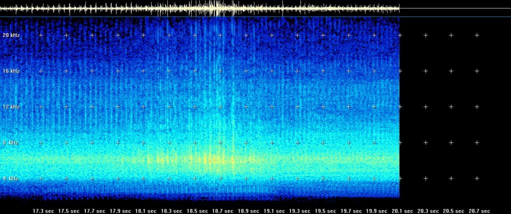
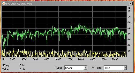
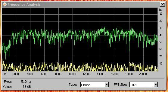
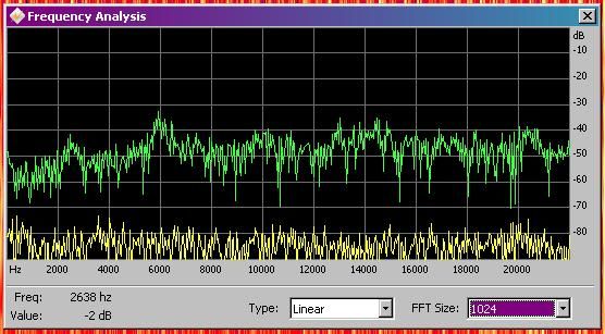
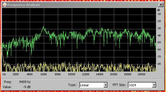
The test engine is a 4 cylinder and has 100 mm pistons so 5.73 kHz is the calculated frequency. If you look at the unfiltered plot, there is always some "knock energy" present around that frequency. As for the other bands of frequencies, I don't care about them getting filtered out.
In the bandpass region of the filter the engine is relatively quite, so that was another reason to design a filter in that region.
There was an additional 30 dB added to the digital filter to get more “filtering” onto the signal.
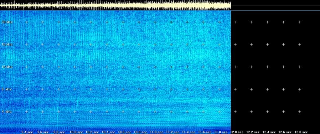
The beating across the time domain of the plot is certain combustion events within the engine. The knock sensor is physically located closer to one of the pistons (H4 engine design). This test was at ~3000 RPMs or 50 RPS. There are 2 ignition events for each revolution or 100 sparks per second. The knock detector is picking up every forth combustion event.
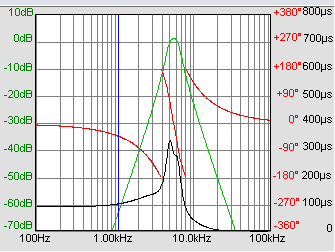
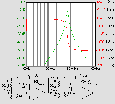
I chose a Chebyshev filter because of it’s steep rolloff. I am only interested in those peaks in the 5.0 to 6.4 kHz range.
Here is a plot for the above Chebyshev filter
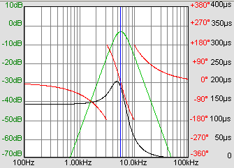
Here is a plot for the Butterworth filter
So the phase change is the same for both filters. There is about 200 µs of delay in the Butterworth and ~300 µs of delay in the Chebyshev. With the knock events spaced apart at 10 ms apart (6000 RPM), I don't believe that 100 µs would mess up the knock signal in the bandpass that much between the two filters.
Here is a spectral plot of the engine with no knock, the engine is ramped up from 3000 to about 5500 RPMs.
![[wink]](/data/assets/smilies/wink.gif "[wink] [wink]")