Continue to Site

Eng-Tips is the largest engineering community on the Internet

Intelligent Work Forums for Engineering Professionals

  • Congratulations KootK on being selected by the Eng-Tips community for having the most helpful posts in the forums last week. Way to Go!

Pivot Plane 2

Status
Not open for further replies.

Kiwing

Mechanical
Dec 15, 2015
7
Dear all,
I am newly registered to this forum, it has already helped me a lot, when I was learning Abaqus. Now for the first time I have a problem where I can't find a solution.

At the end of a long rod, the centre of the surface has to be displaced by a fixed value. At the same time lateral contraction due to Poisson's effect has to be allowed and the plane must be allowed to rotate freely around the centre of the end face.
In other words the end surface has to act as a pivot plane.
I attach a drawing to illustrate this.

How can this be implemented in Abaqus?

I tried the following methods:
*Equation does not help because rotations can become quite large (small angle approximation invalid).
*Kinematic coupling enforces same displacement on all nodes and prevents pivoting.
*Distributing coupling has to be applied to all translational degrees of freedom and will not allow lateral contraction (Poisson's effect).

Any ideas would be highly appreciated!

Thanks in advance
Marco
 
 http://files.engineering.com/getfile.aspx?folder=9d7cbc84-23ba-4b0d-9eaa-bdf1e8ec6c25&file=PivotPlane.png
Replies continue below

Recommended for you

Hi,
What about making a local coordinate system at the tip of the beam.
Then making a coupling that allows for all movement except axially and refering to that local coordinate system. After that, you create a set of nodes of the nodes at the end of the beam. On this set you apply the concentrated loads you want.

It is just a guess. I could be wrong. Do you have a model to verify if it works or not?

Best regards,
 
Hi,

attached are a hand-written input file to illustrate the problem and two screen shots of the results.

As the displacement boundary conditions at the tip needs to be both, in axial and lateral directions, I don't see a way to allow for lateral contraction and displacement BCs.

I tried a lot, but I didn't get the desired results using kinematic coupling, however, I have almost no experience using it. Maybe there is a way using a local coordinate system in combination with the kinematic coupling constraint?
Can you please help?


Kind regards
Marco
 
That kinematic coupling with a orientation could work.

Maybe I have another idea. 'depends...

But a question first. How/where has the load to be applied?

a) at the center node of that face
b) at all nodes of that face
c) at a reference load with something at it, that distributes it to the nodes at the face
 
Hi,
So I have given it another try, but still I can't get the transversal contraction out of the system, what ever kind of local coordinate system I use.

I tried using a node based (co-rotational) system:
Code:
*Orientation, name=TipCsys, system=rectangular, definition=nodes
406, 411, 407

And a local Cartesian system at the tip, defined by
Code:
*Orientation, name=TipCsys, system=rectangular
1,0,100, 0,1,100, 0,0,100

with
Code:
*Coupling, constraint name=KinemCoupRP, ref node=TopRPSet, surface=TopSurf, orientation=TipCsys
*Kinematic
1, 3


Still, I am always lacking lateral contraction at the pivot surface, however, I'm not sure whether I understood and implemented your proposals correctly.

The load has to be applied as a displacement boundary condition at the centre of that face, not necessarily on any specific node. The displacement BC needs to be such, that the surface remains flat (no pull-out) and lateral contraction needs to be permitted (Poisson's effect). So in principle all three cases would be fine, the displacement can be enforced on all nodes of that face, with a reference node or any other node on that face.

Kind regards
Marco
 
You are applying forces along both the length of the beam and to the side, correct?
 
Yes, correct, I apply a displacement along both the length and to the side (however, only displacements, no forces).
 
Maybe this works:
Create a analytical rigid surface. Position it at you beam face. Use a center node at the beam face as reference node. Create a contact of the other nodes to the rigid surface with the adjust parameter. As behavior use frictionless and no separation. Apply the displacement at the reference node. Maybe you have to use a small friction value in contact to remove the remaining rigid body motion.
 
Hi,

Following kinematic constrain definition should do the trick.

Code:
**
*ORIENTATION, NAME=PivotPlaneOri, SYSTEM=CYLINDRICAL
 0.0, 0.0, 0.0,  0.0, 0.0, 1.0
**
*COUPLING, CONSTRAINT NAME=KINEMCOUPRP,
           REF NODE=TOPRPSET,
           ORIENTATION=PivotPlaneOri,
           SURFACE=TOPSURF
*KINEMATIC
2, 3
**

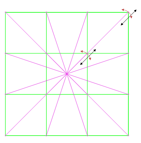
I see one limitation. Nodes movement on the plane is not completely free.
They can deform along black directions but can not rotate along red directions.

constrain_biwb0n.png


If this is a problem for you the idea with contact plane from Mustain3 sounds interesting.

Regards,
Bartosz

VIM filetype plugin for Abaqus
 
Thank you very much, this is exactly what I was looking for!

Apparently I don't fully understand the kinematic coupling function. Why is it sufficient to couple displacements in circumferential and Z-direction if the reference node is displaced in X-, Y- and Z-direction?

I had tried a similar arrangement, swapping coupling in circumferential direction with radial direction, however, this doesn't converge. Why?
 
Status
Not open for further replies.

Part and Inventory Search

Sponsor