Continue to Site

Eng-Tips is the largest engineering community on the Internet

Intelligent Work Forums for Engineering Professionals

  • Congratulations KootK on being selected by the Eng-Tips community for having the most helpful posts in the forums last week. Way to Go!

Planes or views on custom coordinate plane

Status
Not open for further replies.

bjlasota

Mechanical
Feb 28, 2019
42
Good morning,
I'm working with a design done by someone else, who designed the complex part in place(not on the standard coordinate plane). I have entered a custom coordinate plane and would like to generate a top, right, and front view plane based on the x,y,z of the new coordinate system. This is only used for generating the print. What is the best way to build views off the new coordinate system?
I should note that many assembly drawings have already been generated, so I don't want to modify the existing coordinate system, I have to build individual component prints.
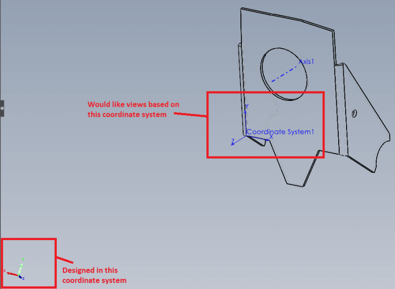
View_s9ss0a.png


Brandon LaSota
CAD Engineer
Modineer
 
Replies continue below

Recommended for you

Make normal to new plane. Right-click somewhere in blank area (not on model), select "Select current view as", select view as needed. Do to all 3 planes as needed.

ctopher, CSWP
SolidWorks '19
ctophers home
SolidWorks Legion
 
SW's coordinate systems still haven't caught up with where NX's and Creo's were 25 years ago.
 
bjlasota,

When I ran into your problem, I drew 3D sketches that defined the planes for my drawings. These were parametrically linked to my model. I used the sketches to create planes. I re-edited the sketches so that there were no longer parametric, and I moved the sketches and plane up ahead of my 3D model.

--
JHG
 
drawoh,

That's not a bad idea, but a lot of steps. It seems as the planes in SW match up with the default coordinate system. I was trying to find a way to define new planes based on a new coordinate system that wouldn't affect messing up all my current drawings and views. But, what you provided is a solution.

Brandon LaSota
CAD Engineer
Modineer
 
In the part model, orientate the part how you want it to appear in the drawing view. If you want to be looking normal to a face, select the face and click "normal to". Then hit space and save the view. Then, when you insert a drawing view you can select that custom view model orientation.

Am I missing something?

-- SirPhobos
 
SirPhobos,

The part was designed in space. So there is no way to orientate the part squared up due to the geometry of the part and just a face and normal to. However, someone above did say by selecting 2 faces then normal to, you have more control over the parts orientation. This solved my view issue, then I was able to save custom views.

Brandon LaSota
CAD Engineer
Modineer
 
You can always do a "move body" and move it back to the origin using mates (probably the easiest thing to do) if you need to. YOu can also edit the initial sketch and bring it back to the origin. I have done that a lot. Yes, it messes up the other sketches, but if you do your due diligence on the sketches after the initial feature beforehand then you can basically have it built at its origin instead and on whichever plane you want it on.

Hope that helps,

Scott Baugh, CSWP [pc2]
Mechanical Engineer
Ciholas

"If it's not broke, Don't fix it!"
faq731-376
 
Status
Not open for further replies.

Part and Inventory Search

Sponsor