Continue to Site

Eng-Tips is the largest engineering community on the Internet

Intelligent Work Forums for Engineering Professionals

  • Congratulations SSS148 on being selected by the Eng-Tips community for having the most helpful posts in the forums last week. Way to Go!

Plastic Analysis 1

Status
Not open for further replies.

ILLINI99

Structural
Aug 19, 2010
11
I am looking for a book that gives a good example of plastic analysis for a beam. What I am specifically looking for is a single span beam with a fixed end and a pinned end with a point load that is large enough to partially yield the section. Does anyone have a good reference, as I have not found anything helpful.

Thanks in Advance.
 
Replies continue below

Recommended for you

Are you looking for a collapse load or something else? I'm not sure I completely understand what you need. You can find collapse load solution on youtube, for example on is exactly the problem you described if I understood correctly.
 
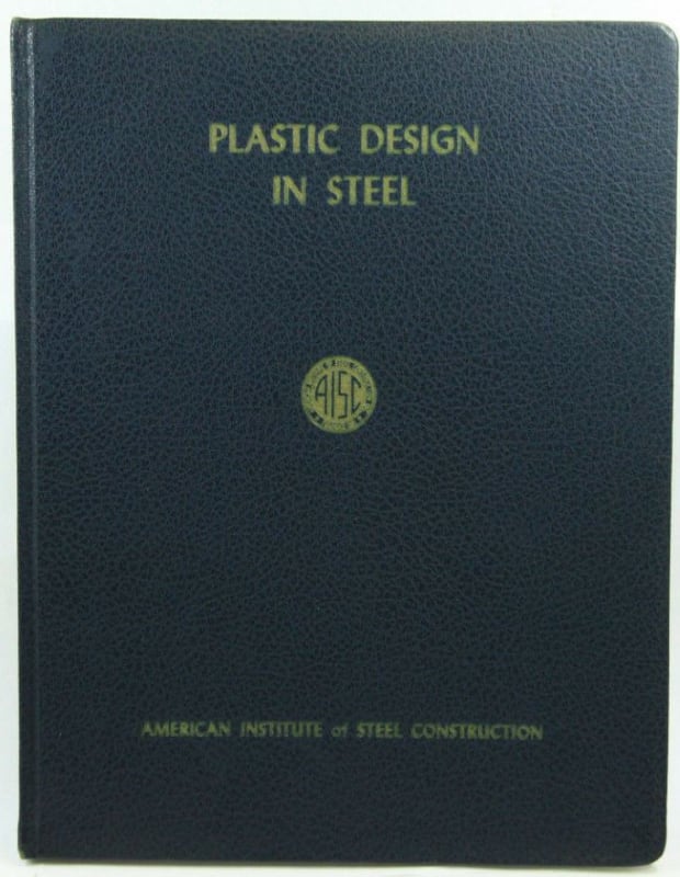
My top recommendation would be the publication shown below. If you can wait a few days to receive it, you can probably pick it up on ebay/amazon for pretty close to nothing at all.

c01_h0zakd.jpg


HELP! I'd like your help with a thread that I was forced to move to the business issues section where it will surely be seen by next to nobody that matters to me:
 
hardbutmild,

I have a beam that has permanent deformation from a point load, and I am trying to determine the load that caused it. I am trying to keep the analysis as simple as I can, as I will likely be doing this by hand. Given that it a single span and the type of supports, it is likely someone has solved this before and it is published, I am just unable to find it.
 
Are you just looking for the theoretical load that could have caused the permanent deformation, or are you looking for an accurate estimate of the actual load that was applied? I feel like these two values could be quite far apart.

On the theoretical side, I think it would be as simple as determining the moment at which the beam section yields, and then calculating the point load that induces that moment given the span and support conditions. This theoretical value wouldn't consider the actual yield strength of the material, the actual cross sectional dimensions (compared to the book values), and the fixity of your fixed end.

If you're looking to get an accurate estimate of the actual load that was applied, I think its going to get somewhat complicated. Among other things, I think you'd need to determined:

[ul]
[li]The actual fixity you're getting at the fixed end[/li]
[li]The actual yield strength of the material[/li]
[li]Accurate cross section of the beam[/li]
[li]Accurate measurement of the existing deformations[/li]
[/ul]
 
Canpro,

I have measurements and the x-sec and I know that my boundary conditions and material properties are as reasonable as I will be able to get given this situation. My problem is I can calculate a yield load (load when My first occurs) or a collapse load (Mp), but do not have an easy solution for something that is between the two.
 
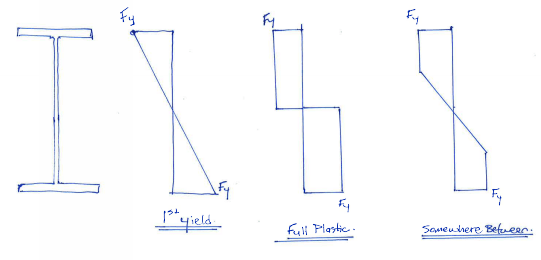
I might be oversimplifying this part, but I think calculating the moment value between first yield and full plastic is fairly straight forward, per the below sketch. But I think the real challenging part is (assuming you need to do this) determining at which point in between the two values the beam is at right now. I think you'd need a survey of the beam to determine the deflection along the length (giving you slope and rotation), which should allow you to calculate the current state of stress in the beam. But I'm assuming the point load is no longer applied to the beam, so you'd have to work backwards to determine what load was applied in order to "lock-in" that much stress.

What is the end-game here? Currently you're able to say that the applied load was at least "Y" (1st yield) but likely less than "P" (full-plastic)...how accurate do you need to get between those two values?

beam_stress_dhun0e.png
 
What else can you tell us about the problem? Did the section at the fixed end yield, just the one under the load or both? This seems like a complex problem if you want a good approximation and to only use hand calculations, I doubt there's an example in any of the books.
 
The deformations combined with the yield strain should tell you how much of the section has yielded. From there, if I'm thinking about this correctly, it's a matter of summing the moments as F * A * y, where F is the average stress (equal to the yield stress for the areas that have yielded), A is the area of the section, and y is the distance from the center of the force to the neutral axis./ The center of the force is the centroid of the area for the yielded areas, and the distance to the point where 2/3 of the area is on the neutral axis side (2/3 of the distance to the line of yielding for rectangular sections) for areas that remained elastic.

Edit: I see CANPRO has added an illustration for what I was saying. Just separate the areas at the inside edge of the flanges and the transitions between the rectangular portions of the stress diagram and triangular portions. If your beam is that simple, you'll have just 6 areas to sum the moments from. That should give you the moment at the point of yielding (where the plastic deformation occurred).

 
Canpro,

I am looking at an impact on the bottom flange of a beam. The fixed end and pinned end boundary conditions were reasonable assumptions given the beam I am looking at. I am looking at the effect on only the bottom flange to make calculations a little easier.

I am trying to determine how much of the section is currently at yield stress. This is to aid in determining the current capacity of the beam. I would like to calculate the load applied based on the permanent lateral deflection of the flange.
 
That changes things a bit, but if I'm not mistaken, it actually simplifies it, if only the bottom flange yielded and the rest of the beam is still elastic. If you ignore the small amount of elastic torsional force from the top flange and web that's reducing the lateral displacement, you only need to apply the principles outlined by CANPRO and myself to a rectangular beam and rearrange the equation from the applicable beam diagram in the AISC steel manual (#14 in 2nd Ed. LRFD).
 
1) Because there is no external load, the locked in stresses in the flange will be self equilibrating. And you can take advantage of that by assuming that, under full design moment, the locked in stresses in the flange would "pull through" and eventually achieve the same stress distribution that would have occurred in the absence of the impact damage.

2) If the impact damage occurred to a flange always in tension, I feel that #1 makes it such that you're good to go: same capacity as the undamaged beam.

3) If the impact damage occurred to an unbraced flange in compression, you can still push through the stress field as with #1 but you'll have to consider the impact that this may have on local and lateral torsional buckling. And I'm not sure that there's a reliable way to assess that without getting stupid-fancy on the problem. If it were me, I'd do one of the following:

a) find a way to straighten the thing if possible.

b) add some new lateral bracing at and near the damage.

HELP! I'd like your help with a thread that I was forced to move to the business issues section where it will surely be seen by next to nobody that matters to me:
 
Excellent summary, KootK. I thought about posting something similar, but I kept rolling with how to calculate the impact load, in case the OP was attempting to do some sort of forensic analysis of the impact magnitude.
 
Thanks for the kind words HR. We're always in a state of guessing OP intent to some degree. And that's not a knock on the OP here. There's just always something lost in translation when an OP pares their problem down to just the bits they think will be appropriate for us to consider.

HELP! I'd like your help with a thread that I was forced to move to the business issues section where it will surely be seen by next to nobody that matters to me:
 
KootK, I understand the logic in what you're saying - if the beam is loaded (strong axis bending) the lateral kink in the bottom flange will tend to straighten out as the beam deflects downwards, which will remove the residual stress from the impact. But is there any guarantee that the bottom flange will return to a straight line before it reaches its limits in strong axis bending? As the beam is loaded vertically, there will be additional stress added to the bottom flange from the strong axis bending, but at the same time, some residual stress removed as the flange straightens - I'm not sure how you would compare the rate of stress being added vs removed, but it seems like something that should be checked.
 
CANPRO said:
But is there any guarantee that the bottom flange will return to a straight line before it reaches its limits in strong axis bending?

No guarantee unless it reaches plastic moment resistance. And maybe not even then. Regardless, I don't see a negative consequence associated with this outcome for a tension flange.

CANPRO said:
I'm not sure how you would compare the rate of stress being added vs removed, but it seems like something that should be checked.

I'm not sure what one would check for a tension flange. What negative outcomes concern you?


HELP! I'd like your help with a thread that I was forced to move to the business issues section where it will surely be seen by next to nobody that matters to me:
 
Interresting question. I have actually done a similair analysis a few years back. In my situation it was dynamic loading that resulted in a "knee" on a column due to local plastic deformation.

What we did was to determine the load required to get a known plastic deformation. Basically a load-unload scenario to get the correct final deformation for the unloaded column. But since it is partial yeilding involved you can have a complex stress situuation in the cross section. We used non-linear dynamic FEM-analysis, primarily because our loading was fairly "high speed".

The ting is that the resulting stresses in the unloaded section can be complex since part of the section has yeilded. You have plastic strains combined with elastic strains and while the elastic strains want to return to zero, the plastic strains will hinder that resulting in a mixed stress distribution.

Thomas

 
Kootk/Canpro,

Please note this is a second attempt on this issue that I am looking at differently than I did the first time. Here is a brief description of what I originally did.

I initially looked at this based on the deflections measured in the area of the impact and used the radius of the deflected flange to calculate the "bending" strains after the impact. I used this as the final condition with the tension strain in the flange also added. I then calculated a bending strain "beyond" that would allow the flange to "relax" to the measured strains after impact.

Please note that I had to adjust these calculated strains by adding an "adjustment strain" to maintain zero lateral moment and the correct tension force in the flange.

Here are the original results in the attached file. Blue is at impact and green is after.

I was asked to take a look at it differently, which is what I am currently working on as discussed in the posts above.
 
 https://files.engineering.com/getfile.aspx?folder=1a9bfd72-2bb9-4bd8-86c6-47ded9681ef8&file=stress_strain_diagram.pdf
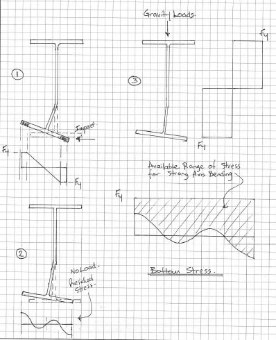
KootK, I don't think I articulated my question/concern very well...in thinking of a better way to word what I was trying to say, I may have sorted it out myself. See sketch below.

Stage 1 is moment of impact, and some portion of the flange tips yield. Stage 2 is when the load is released, the flange rebounds some distance and is left with some residual stress. I was thinking that if the flange didn't return to its true alignment while being loaded in the strong axis, there would be some amount of residual stress remaining that would reduce the strong axis bending capacity. That takes us to stage 3 where the beam is loaded to its full plastic capacity - the side of the flange that was in tension due to previous impact has a limited amount of additional stress it can handle before it reaches Fy, but the opposite side that was in compression can change its state of stress by some value greater than Fy...I believe what you were saying is that these effects cancel each other and we're all good to go.

impact_asxsfq.jpg
 
CANPRO said:
...I believe what you were saying is that these effects cancel each other and we're all good to go.

Precisely. One nuance is that the new residual stress distribution will alter the value of Ix & Iy a bit over the load history of the member. Some parts of the cross section will yield and give up their stiffness contribution earlier in the load history. Others, later. This isn't all that different from the state of affairs with regular residual stresses, however, and I'd not expect it to appreciably affect overall member performance. At some point you just have to accept that everything is approximate and choose to spend your time where meaningful impact can be had.

HELP! I'd like your help with a thread that I was forced to move to the business issues section where it will surely be seen by next to nobody that matters to me:
 
Status
Not open for further replies.

Part and Inventory Search

Sponsor