Continue to Site

Eng-Tips is the largest engineering community on the Internet

Intelligent Work Forums for Engineering Professionals

  • Congratulations SDETERS on being selected by the Eng-Tips community for having the most helpful posts in the forums last week. Way to Go!

Plastic Capacity and Shear Flow 2

Status
Not open for further replies.

iStruct

Structural
Jan 2, 2020
12
I have done a lot of steel retrofit and usually this involves welding a plate to a beam or similar. Often it is more economical to use the full plastic capacity to get the plate size if top flange is braced.

If I am using the plastic capacity of the plate it seems wrong to me to then use VQ/I to size the welds considering I need to transfer more through the weld than if it were just elastic bending. I am thinking that the welds would be sized similar to how studs in a composite beam are sized/spaced. Am I crazy? I have seen some text book examples where VQ/I is used where it is expected the beam develop full plastic capacity.
 
Replies continue below

Recommended for you

We use VQ/I for fatigue design of studs in composite bridge girders.

Under the AASHTO bridge design spec., I don't believe there is a 'yield strength', only the 'tensile strength', which I assumed to be the ultimate (fracture) resistance.


I think I misunderstood the OP. Now that I've reread it, I think you're saying you should be using the higher force associated with plastic moment capacity to design the weld. If so, I think I would agree. The strength design for shear studs in composite bridge girders is essentially approached that way - shear on the weld is calculated assuming he entire steel girder is in tension.

Rod Smith, P.E., The artist formerly known as HotRod10
 
I have had the exact same thought. I got through it by mentally replacing shear, V, with the change in moment per weld spacing, dM/dS, and seeing the welds as jumps in my moment capacity. Now, I realize that I probably am developing the plastic moment, even though the derivation uses shear and moment of inertia.

Designs using that equation are for concentrated loads PL/4, where P = 2*V.
 
Thank you @BridgeSmith and @RPMG. I attached a "proof" where I tried to show what I am thinking on this. Take a look and let me know what you think. I am studying for the SE and trying to get my P's and Q's in order, thanks for your help! Happy New Year!

 
 https://files.engineering.com/getfile.aspx?folder=f4211a34-8dc4-46e8-b9ee-722d7be87c5d&file=ShearFlow.pdf
I think I misunderstood the OP. Now that I've reread it, I think you're saying you should be using the higher force associated with plastic moment capacity to design the weld. If so, I think I would agree. The strength design for shear studs in composite bridge girders is essentially approached that way - shear on the weld is calculated assuming he entire steel girder is in tension.

Yes! My opinion is that to achieve plastic capacity you will need more weld, for a flange plate retrofit, than you get when using elastic shear flow(VQ/I). That is what I tried to proof in the attachment.
 
This AISC webinar had some info on the topic, can't seem to find the link to the recording and my memory is little foggy but they still recommended VQ/I for the intermittent welds as a minimum. Your beam is only fully plastic at the point of maximum moment so an elastic model is still valid for a chunk of the beam span.

AISC Live Webinar - February 18, 2016

Open Source Structural Applications:
 
For the situation you're considering, it seems correct to consider the plastic section.

For the weld design work that I do (plate girders mostly), the difference would be fairly small, since the welds are near the edge of the section (at the inside faces of the flanges), so the stress doesn't change significantly moving from the extreme fiber to the weld location. Perhaps that is reason the VQ/I is considered acceptable in many cases.

Edit: Combine the aforementioned minimal difference in stress with Celt83's observation that typically only a small portion of the beam goes plastic, and the difference in the demand on the overall weld length is indeed very small. (For a plate girder or a flange cover plate for an "I" girder, anyhow)

Rod Smith, P.E., The artist formerly known as HotRod10
 
Thank you @ Celt83. That power point by AISC is gold. Slide 111 says that the ends of a retrofit WT welded to an existing beam are welded at the ends for "full yield". This to me means the tensile capacity of the new member. Then they provide VQ/I intermittent welds as kind of a safety factor. I like it, thanks so much!
 
I don't really follow your sketch - why are you dividing by 6"? In any case the welds you calculate for shear flow are intended to get the cover plate and the beam to work together, not develop the strength of the cover plate. That is what the anchorage length is for, and if you use plastic section modulus it should develop the plate strength. Intuitively for cover plates on wide flange sections, I would think VQ/I would be quite conservative for the plastic stress distribution (but you have to be elastic first to get there), and I think that's what slide 111 is getting at. I suppose anything near the plastic neutral axis should be sized so that the material on either end of the weld can yield without failing the weld, but that is an uncommon location for reinforcing.
 
@canwesteng

The 6" is from the point of max moment to the point of zero moment for my 12" long beam. I do agree that the anchorage length is there to ensure full composite action while the VQ/I for the rest of the beam is conservative.
 
VQ/I is to ensure composite action, anchorage length is to develop the plate fully for the design moment. I guess now I'm even more confused by your sketch, it seems like numbers that work out because of coincidence rather than anything else.
 
The slides from AISC made me believe that the welds at the end ensure composite action. The welds in the middle could be the minimum required but it is good practice ("prudent") to do VQ/I for those welds. AISC F13.3 requires that welds be placed in proportion to vert. shear that is why the big welds at the ends.

If you are only counting on the beam yielding elastically then you could use VQ/I to ensure composite action per slide 110. Because AISC F13.3 requires that the "horizontal shear attachment is distributed in proportion to the shear" you would use Mc/I to get the max stress then max stress x area of reinforcement to get the welds at the ends. To me this is different than a plastic section where you would need Fy * As ("full yield") for the end welds. If I were welding a big WT to a beam it could make a difference in the length of weld.

I did the proof again (attached) with different numbers and got the same type of result. My steel professor at University of Illinois kind of got me on this concept of shear flow for composite beams. To me it is much simpler than how text books teach it. I just think of it as the compression and tension from flexure trying to shear the beam horizontally.
Thank you for commenting on my post. This is my first post in EngTips. I read through the whole Miami bridge collapse thread and was hooked.
 
 https://files.engineering.com/getfile.aspx?folder=057fd303-6a92-4a51-9f78-f69d3dea32c0&file=ShearFlowRev1.pdf
iStruct said:
This is my first post in EngTips. I read through the whole Miami bridge collapse thread and was hooked.

Welcome to the community, we look forward to your contributions.

Some thoughts on your problem:

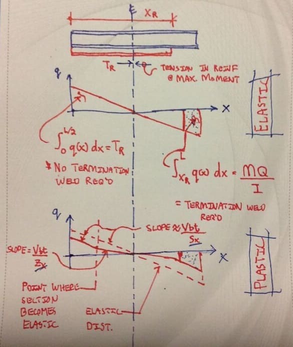
1) For the same set of internal actions (moments and shears), the shear demands on the welds will actually be less under the plastic model than they would be under an elastic, VQ/It. That's right, less and not more. I know, it's counteractive for most folks and certainly was for me when I started out. This is physically reasonable because, for the same moment, a plastic distribution will shift some of the axial stress out of the flange into the web such that it never sees the flange to web welds. For folks in the know, this is why you commonly see VQ/It use for plastic moment situations. It's expedient, conservative and, like Celt83 said, much of the beam remains elastic anyhow.

2) In a strict sense, both your intermittent welds and your end welds are doing the same thing: ensuring local horizontal shear demands are met close to where they naturally arise. That, so that composite action can be developed and the assumed, reinforced moment capacity can be reached. There's no "belt and suspenders" stuff going on unless designers deliberately add that which I'll tough on below.

3) In a strict sense, the end welds are not required if the reinforcing makes it all of the way out to the ends of the beam. It is only required if the reinforcement stops short of the ends of the beam which is often the case for practical reasons. That said, most everybody includes some form of end welding just to feel good about how things "get started" from a stress flow perspective.

4) In a strict sense, the purpose of the end welds is to rapidly introduce axial stress into the reinforcing so that, as quickly as possible, the reinforcing can be assumed to be sharing demand in an MQ/I manner similar to what you described in your last post. Quantified, that value is MQ/I and represents the intermittent, VQ/It welding that would have been present over the portion of the reinforcing not extended to the end of the beam if, in fact, that reinforcement had been extended to the end of the beam. See the sketch below.

5)#4 excepted, it is common for designers to fully develop the axial capacity of the reinforcement with the end welds. This does seem to be a conservative, belt and suspenders thing. The usual business about small $$$ begetting improved sleep. I don't ascribe to this myself and sometimes feel that it might be a vestigial hangover from the case of bar joist reinforcement where the practice is more applicable. I'll default to 6" end welds of the same size as the intermittent welds and only increase that if required by calculation. For a lot of reinforcement sections it doesn't make much difference but, as you pointed out with the WT situation, sometime it does.

c01_bwrjbz.jpg


Consider playing chess with me on the Social Chess app at iTunes. Same handle. Fear not, I suck.
 
I just downloaded a guide from AISC. In the example they sized the welds at the cutoff points for the Fy * Ag. Then they used a minimum 1/8" x 2" weld at 12" on center for the intermediate welds. No calcs required for the intermediate welds. They didn't use VQ/I. This kind of goes with what I was saying that the VQ/I is a bit of a safety factor for the intermediate welds if you use Fy*Ag at the ends. To me this seems quick and simple. The guide is "Strengthing of Existing Composite Beams Using LRFD Procedures".

I do get what you are saying that for portions of the beam it will be elastic and in those portions the reinforcing member will see less force. In those areas Vmax*Q/I could be conservative. I also agree about the intermediate welds and the end welds doing the same thing. Personally, I would want at least some portion of my member to have bigger welds to account for the plastic force transfer. But yes I agree that if you run the reinforcing to the ends, in theory you could just use a minimum weld there.
 
iStruct said:
No calcs required for the intermediate welds. They didn't use VQ/I.

Sounds nuts to me. You're referring to this article: Link? Can you post the relevant bits here so that we can review them?

iStruct said:
This kind of goes with what I was saying that the VQ/I is a bit of a safety factor for the intermediate welds if you use Fy*Ag at the ends.

Vehement disagreement from me on this. The end welds on their own cannot ensure meaningful composite behavior. This situation is different from the composite shear stud scenario in one massively important way: shear studs can be thought to be ductile with respect to horizontal shear and welds cannot. As a result, welds need to provide the required shear flow capability very close to where demand arises without relying on significant force distribution as we do with composite shear studs. This is why AISC has that provision instructing you to provide capacity in accordance with your shear diagram.

OP said:
I do get what you are saying that for portions of the beam it will be elastic and in those portions the reinforcing member will see less force. In those areas Vmax*Q/I could be conservative.

VQ/It will be either safe or conservative absolutely everywhere along the length of your plastically designed beam. Every. Where. Without exception.

iStruct said:
Personally, I would want at least some portion of my member to have bigger welds to account for the plastic force transfer.

There is no rational basis for this as the plastic model demand will be less than the elastic model demand everywhere and always.

 
Ah yes that is the article. I would post it but people are supposed to pay for it. Can you download it?
 
No luck so far. With respect to intellectual property rights, we seem to implicitly accept this ethical compromise around these parts:

1) Don't attach the entire document unless it's public domain.

2) Do post select clips from the document if they would allow us to see the important bits of what you're seeing.
 
Thanks.

- How do they calculate Tr?

- In the last paragraph, where they mention the minimum requirements, I would suggest that either:

a) VQ/It perhaps was calculated but the results have not been shown or;

b) the author is applying judgment in assuming that the 2" @ 12" welds would be sufficient for VQ/It.
 
There is another feature of that particular example that may be important / telling. With a paltry 4.8' of reinforcement in the center of a 40' beam, you'll be on the flat portion of the moment diagram in most cases and very little horizontal shear would need to be transferred over the length of the reinforcing plate. The author may well advocate a more conventional approach, including VQ/It checks if it were, say, 30' of reinforcing over a 40' beam. In light of the proportions used in the example, that simplified approach does makes sense to me. That said, I would not advocate it's use in general.
 
Status
Not open for further replies.

Part and Inventory Search

Sponsor