Continue to Site

Eng-Tips is the largest engineering community on the Internet

Intelligent Work Forums for Engineering Professionals

  • Congratulations IDS on being selected by the Eng-Tips community for having the most helpful posts in the forums last week. Way to Go!

Plastic Capacity and Shear Flow 2

Status
Not open for further replies.

iStruct

Structural
Jan 2, 2020
12
I have done a lot of steel retrofit and usually this involves welding a plate to a beam or similar. Often it is more economical to use the full plastic capacity to get the plate size if top flange is braced.

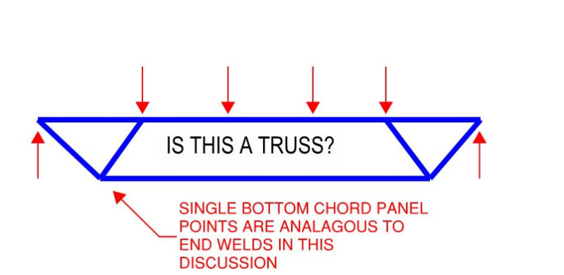
If I am using the plastic capacity of the plate it seems wrong to me to then use VQ/I to size the welds considering I need to transfer more through the weld than if it were just elastic bending. I am thinking that the welds would be sized similar to how studs in a composite beam are sized/spaced. Am I crazy? I have seen some text book examples where VQ/I is used where it is expected the beam develop full plastic capacity.
 
Replies continue below

Recommended for you

Tr = Fy * Ag = 36ksi x 2.02 in^2 (WT6x7 Gr. 36)
 
Thanks. I stand by my last post.

I'm jealous that you managed to get the handle iStruct. As long as this forum's been around, I'd have thought that would have been taken long ago.
 
Also here is a quote "Since the tensile capacity of the reinforcing section is resisted by the welds of the cut-off points, and compression stability is not an issue, the designer needs to only consider a weld spacing that satisfies the requirements for built up tension members given in the LRFD specifications. Generally, weld spacing should not exceed 24 times the thickness of the thinner element nor 12 inches." They also have a step by step guide that doesn't include the VQ/I.

I just read through the built up tension spec in AISC it just talks about spacing not exceeding 6" and keeping the slenderness ratio of any component between the spacings to 300.

Alright I'm off to be a Dad. Have a good weekend!
 
In the article "Tr" is defined as the required force in the reinforcing and is calculated as follows:
article_snip_1_lxdpba.jpg

article_snip_2_pgkpcl.jpg

article_snip_3_aqkh2t.jpg
 
iStruct said:
Also here is a quote "Since the tensile capacity of the reinforcing section is resisted by the welds of the cut-off points, and compression stability is not an issue, the designer needs to only consider a weld spacing that satisfies the requirements for built up tension members given in the LRFD specifications. Generally, weld spacing should not exceed 24 times the thickness of the thinner element nor 12 inches." They also have a step by step guide that doesn't include the VQ/I.

Sure but, again, unless all of that applies to a reinforcement set out over enough beam span that meaningful shear transfer is required between the ends of the reinforcing, it doesn't prove anything.

iStruct said:
I just read through the built up tension spec in AISC it just talks about spacing not exceeding 6" and keeping the slenderness ratio of any component between the spacings to 300.

You're not suggesting that the minimums specified in AISC imply that nothing else needs to be done are you? Obviously, the standards expect us to do the "engineering" stuff as it makes sense to do so even if they don't explicitly say as much.

iStruct said:
Alright I'm off to be a Dad. Have a good weekend!

As in go play with the kids or head off to the hospital to see one birthed? If it's the latter, get gone.
 
I just got to leave work and go home where I am on Dad duty. My interpretation of the guide is that it was meant for all situations. I would think it would be silly to make a guide for only short length reinforcement.

I do know that there is "engineering stuff" that has to be done which is the plastic analysis and then developing the ends of the WT to ensure composite action. Likely we will have to agree to disagree but for what it is worth I would likely size the end welds for Fy*As and see whether VQ/I or the minimums control for the rest.

Also they do say on the AISC provided slide 105 that MQ/I is only applicable if section remains elastic. Doesn't it seem odd that one would use plastic section modulus for design then use moment of inertia for the connector?

@dauwerda They do use Tr in multiple places like when they do the plastic analysis and then again in Step 5 for sizing the weld at the ends.

I really appreciate everyone's input. I definetly think there is some good debate going on right now.

 
iStruct said:
Likely we will have to agree to disagree...

I don't have that setting. I view every "agree to disagree" as a wasted opportunity for smart people to suss out the truth. That said, if you wish to disengage, there will certainly be no hard feelings on my end.

iStruct said:
I do know that there is "engineering stuff" that has to be done which is the plastic analysis and then developing the ends of the WT to ensure composite action.

AND providing for shear flow between the end welds. Doing otherwise is akin to calling the thing below a truss.

iStruct said:
Also they do say on the AISC provided slide 105 that MQ/I is only applicable if section remains elastic.

1) How much stock do we really want to put in one set of PDF slides with an unknown author? It's worth remembering that, often, these things are put together by other engineers just like us. And, therefore, our opinions are just as valid as theirs. This really is a pretty arcane topic and it would surprise me not at all if the author of the slides was not fully aware of the nuances.

2) By "not applicable", the author of the slides may well have meant "not strictly accurate", which is of course true. However, a thing need not to be accurate if it is universally conservative, not excessively conservative, and expedient as the VQ/It method would be in this situation.

3) This topic was broached by Larry Muir in the July 2014 edition of Steel Interchange. I've included the relevant sections below.

4) For beams composite with a concrete deck, "knowing" the shear flow demand with any accuracy is quite the ask. Back in 2014, I started my own thread on this topic with what I thought were some very interesting observations: Link. Sadly, that was back before I knew how to embed sketches into posts but there are some good sketches included as attachments. The moral of the story is this: for a beam composite with a concrete deck, an accurate determination of the plastic shear flow requirement is pretty much impossible. At that's without considering reinforcement. Viewed in that light, conservatively using VQ/It makes rather a lot of sense. It probably also makes sense to be conservative with the end welding and the location of the cutoff points.

iStruct said:
I would think it would be silly to make a guide for only short length reinforcement.

Me too but, having procured and read the entirety of the article now, that seems to the case. In both the body text and the example, the author is clearly thinking about partial reinforcement as shown below. In my opinion, it was an oversight on the part of the author not to have mentioned the need for distributed, shear flow welding in many situations. It happens. As with with the slides, the author is just another engineer like us (principal at some firm), not a PhD / world authority on the composite mechanics of things.

c03_evbel2.jpg

c01_gdyrac.jpg

c02_da66m9.jpg

c05_waot8b.jpg
 
In New Zealand we have the following two generally accepted equations provided in technical documentation from one of our welded beam suppliers/manufacturers for calculating the weld demand.

Weld_criteria_lskwdg.png


The first criteria is the typical shear flow (VQ/I) requirement written out in terms of section parameters.

The second was initially unfamiliar to me, so I asked, the answer I got back was that it was intended for regions where there is yielding or section plasticity in hinges under seismic loading. Basically its saying take the flange force (b_f x t_f x f_y of the flange )and equate it to a constant longitudinal shear over a length of 1.5 times the clear web depth (1.5 x d_1). This 1.5 originates from the typical minimum plastic hinge lengths we have in our steel code. It inherent that there would be some development of overstrength in the intended condition where this check is applicable, however this isn't explicitly accounted for. I believe the 1.5 factor on the length over which the load is distributed and the strength reduction factors on the welds effectively cover this. Our maximum overstrength for seismic design is a factor of 1.35. Our typical strength reduction factor on welding is 0.8. This level of welding also imparts a degree of robustness under several cycles of an earthquake where a plastic hinge region might be subject to several reversals at a high ductility demand.
 
There is an error in the elastic shear flow equation provided in the July 2014 Steel Interchange response. The equation should have a 'd/2' term in the numerator. The omission has been confirmed by AISC. The other terms in the equation are correct. The shear flow assuming a plastic bending stress distribution, q=(V/Z)bftf, is correct.
 
Hokie93 said:
There is an error in the elastic shear flow equation provided in the July 2014 Steel Interchange response. The equation should have a 'd/2' term in the numerator. The omission has been confirmed by AISC. The other terms in the equation are correct. The shear flow assuming a plastic bending stress distribution, q=(V/Z)bftf, is correct.

Nice find, Hokie93.

Alternatively, AISC/Larry Muir may have meant for the denominator I to be S [ i.e. I = S/(d/2)] and get: (V/S)(1-tf/d)bftf to be in comparative form to his plastic flange force of (V/Z)bftf, which clearly shows that V/Z will be smaller than V/S (and the [1-tf/d] term).
 
Thanks for the update Hokie93. Is there an errata or web link that you could direct me to for that? I'd like to print it off and attach it to my copy of the original article so that I don't loose track of the correction in the future.
 
Status
Not open for further replies.

Part and Inventory Search

Sponsor