Continue to Site

Eng-Tips is the largest engineering community on the Internet

Intelligent Work Forums for Engineering Professionals

  • Congratulations KootK on being selected by the Eng-Tips community for having the most helpful posts in the forums last week. Way to Go!

Plate connection with Stiffener

Status
Not open for further replies.

BendingMoment123

Structural
Apr 1, 2020
25
Hi guys

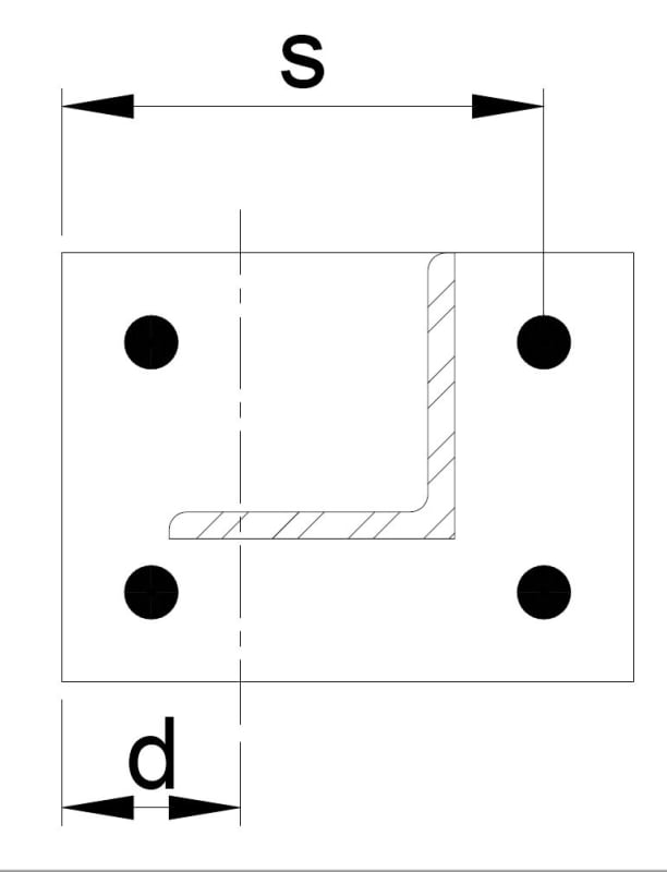
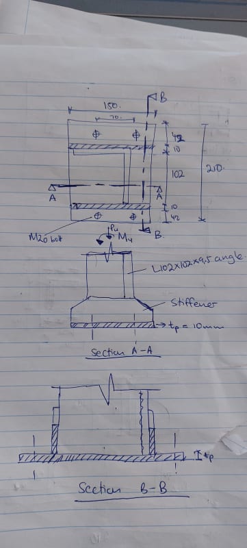
I have an angle section welded to an end plate which is bolted to a steel beam below (Bolts are centred on the plate). Unfortunately, due to geometric constraints, this is the layout I have to work with.

How would you go about determining the bending capacity of the plate. From section B-B, would you calculate the plastic section modulus of the plate and the section modulus of the stiffeners, and then add them together for a combined moment capacity?
20210928_124433_rnjhvs.jpg
 
Replies continue below

Recommended for you

In the vertical direction, the angle and stiffeners are going to be much stiffer than your baseplate. I would expect the base plate thickness to control. To check this, I would apply the largest bolt tension force to the plate and calculate the moment in the plate as the bolt tension force multiplied by the distance to the nearest stiffener or angle surface. Using the allowable stress of the plate and section modulus of the plate, you can design/check the baseplate thickness
 
If you can, it may be less costly to eliminate the stiffeners and use a thicker base plate, and I'd use an effective depth at the angle leg of about 0.85 of the depth of the angle(without the stiffeners).

Rather than think climate change and the corona virus as science, think of it as the wrath of God. Feel any better?

-Dik
 
Thanks guys. If I remove the stiffeners and want to calculate the thickness, would I follow this process:

1. Calculate approximate tension force (Tb) to be taken by bolts = Mu/ angle leg width. The moment will be reduced by compression force Pu, but I will neglect it since its small value.

2. Calculte moment in plate (Mn) = Tb x distance to angle (distance being in direction from right to left as you look at the diagram)

3. Calculate section modulus (Zp) of plate = B×t^2/4 = 242mm x t^2/4

4. Calculate moment capacity of plate (Mp) = Zp×fy

5. Solve for t by equating Mn to Mp
 
Clipboard01_pkvn7b.jpg


Something like... calculate the tension in the anchor rod... Mf/s

Use that force x d to give you the plate moment... and then check with B * t^2 / 4... You might want to check the width of your plate.


Rather than think climate change and the corona virus as science, think of it as the wrath of God. Feel any better?

-Dik
 
thanks for the reply Dik. Just have some questions:
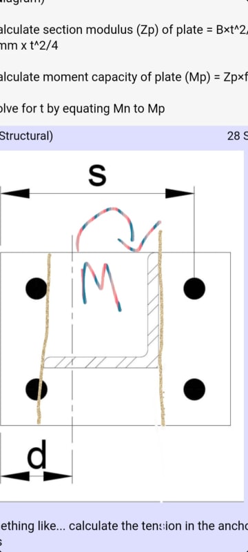
Why did you take distance S from the end of plate to the bolt? Won't the plate failure line be on the brown line as shown below, and then distance D will be from bolt to that brown line. Why did you take distance D as how you have it?

Screenshot_20210928-231807_Gallery_qucpqg.jpg
 
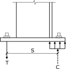
"S" is the distance from the compression force to the tension force. The compression force occurs at the center of the required bearing area which will be some distance from the edge of the plate, but probably not too far since you are bearing on steel, especially if your moment isn't too large.
Base_Plate_Moment_Arm_dz5ebt.png


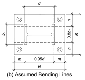
"d" will not be at the very tip of the angle leg. It will be some distance in from there since all of the tension doesn't get transferred into the angle leg at the very tip. It takes some distance, but I don't know of a recommended value for angles. See the assumed bending lines for wide flanges from AISC's Design Guide 1. (Take a look at AISC's Design Guide 1 in general since it explains the design of base plates very well.)
Base_Plate_Bending_Lines_thxhhq.png


For this configuration, I would consider designing the base plate and bolt so that just the bolt that is closest to the tip of the angle takes all of the tension (bottom left bolt in dik's drawing). It is much closer to the angle than the top left bolt so it will take the vast majority of the tension.


Structural Engineering Software: Structural Engineering Videos:
 
Thank you ProgrammingPE. For the Tension force in bolt calculation, I've seen examples being used where they take the applied moment and divided it by the depth of the section.(this was for W/I sections though). This assumes point of rotation from the column flange. Therefore the bolts will pick up the tensile force I'm the flange.

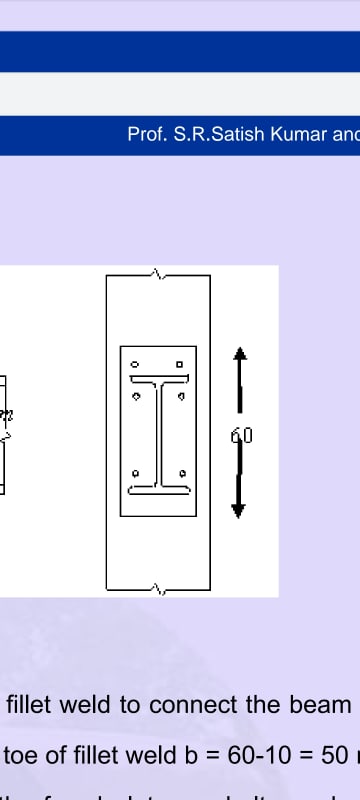
Ex. In the pic below, the total bolt force was determined my taking the moment and dividing it by the depth of the I section.

Screenshot_20210929-072346_Drive_mxghka.jpg
 
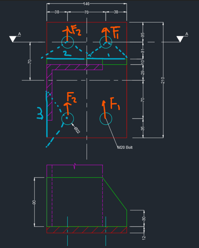
So I basically assumed point of rotation as the edge of the base plate, and determined the bolt forces for each row accordingly. Next step would be to calculate the effective widths of plate used to determine the section modulus. I have identified 3 effective widths highlighted in blue. Are these the correct assumed failure lines to check plate bending? F1 is 12kN and F2 is 4kN.

Widths were calculated by assuming a load distribution of 60 degrees either side of the bolt to the edge of the surface. Moment applied at this width would be force x edge distance.

Screenshot_2021-09-29_152648_xerjdu.png
 
Status
Not open for further replies.

Part and Inventory Search

Sponsor