Eng-Tips is the largest engineering community on the Internet

Intelligent Work Forums for Engineering Professionals

Platform design

Status
Not open for further replies.

Tag_ZEL

Mechanical
Feb 19, 2021
4
0
0
AU
Hi guys,

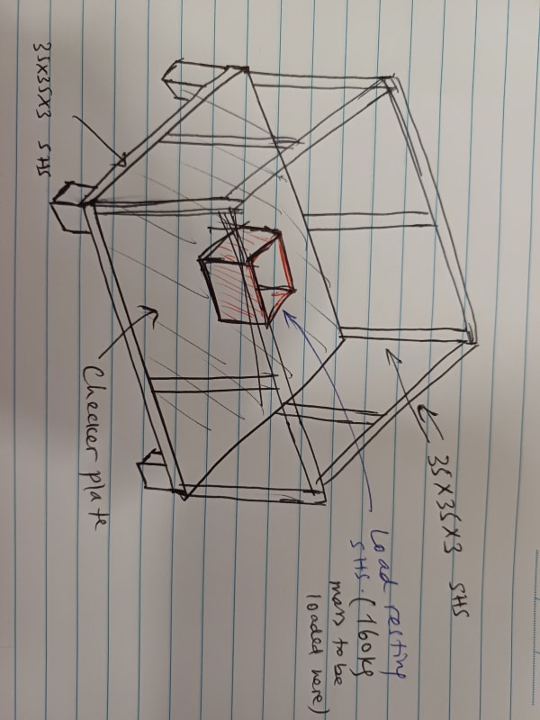
I need some hint on how to verify the design of this jig attached here.

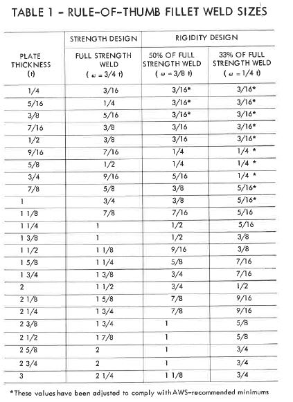
How to calculate weld sizes around the checker plate and SHS.

How to calculate the bending and shear stresses of the members around the checker plate and bottom 4 SHS as well.

Appreciate your suggestions.
20231130_154138_1_pxj4ly.jpg


Cheers
 
Replies continue below

Recommended for you

Checker plate- see Roark's Formulas For Stress and Strain. Table 26, Case 1c in the 5th Edition.
Edge pieces- figure total weight of the checker plate and box, assume supported by two opposite sides only, figure average load/foot and go from there.
You don't say what the application is. If those are handrails, see OSHA requirements and building code requirements for handrail loads.
You may have live or snow load on the checker plate in addition to the box.
On a lot of small stuff like this, you can oversize and under-evaluate more economically than trying to work out "exactly" what the loads are.
Weld sizes on the edge beams could be calculated from an evaluation of the shear forces in the beams. From the looks of it, weld sizes are likely to calculate very small.
 
Thank you JStephen for the feedback.
The jig is actually to be used for transporting a 160kg machine component within the workshop. The component will be loaded on top of the SHS 250x250x6mm which is welded on the middle of the checker plate. Four fully loaded jigs will be stacked together for the storage in the workshop.
 
Unaccountable handling loads will be much higher than any other loads. The attached floor plate load table (or something similar) should help you decide upon a thickness of plate which works with your support structure for the required load, you might be able to find something for point loads. A table of minimum weld size based on plate or tube wall thickness would give you the necessary weld size, and finally, intermittent welds should be 4 x weld size plus 1/4" in length and spaced closely enough to not suffer damage from abuse.

This table is from Design of Weldments by Blodgett, where minimum weld size does not need to be more than the thinner member.
Blodgett_weld_size_zcef0c.jpg
 
Status
Not open for further replies.
Back
Top