Eng-Tips is the largest engineering community on the Internet

Intelligent Work Forums for Engineering Professionals

Please have a look at my application of GD & T 7

Status
Not open for further replies.

sammcc

Aerospace
Jan 21, 2013
103
0
0
IM
Hi all,

I am a novice with regards to the proper application of GD & T.
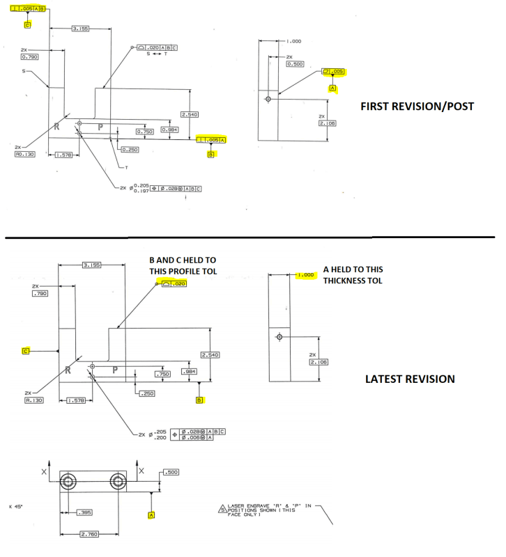
I have attached a drawing of a simple part I have added it to- where previouly it was dimensioned without it.
Can you give me some feedback with regards to the application of the symbols I have used.
I am working to ASME Y14.5 and in units are inches.

Thanks
 
 https://files.engineering.com/getfile.aspx?folder=7afbf985-15e0-468d-9f79-a64375ca10d4&file=doc08946320181012083616.pdf
Replies continue below

Recommended for you

mkcski,

Sorry - you seem to just be explaining the rules of simultaneous requirement vs separate requirement, my questions did not have to do with the basic underlying concept... I am very familiar with how patterns behave when referenced as SEP vs SIM REQT, there is no lack of understanding what they mean. Apologies if I did not make this clear.

What I am trying to understand, and what greenimi seems to be reinforcing, is (1) is the verbiage in 7.5.4.1 vs 7.5.4.2 REALLY saying that separate requirements cannot be applied to DRF's with only planar/non-FOS at RMB and (2) if that is so, the concept also seems to be extended to DRF's with FOS referenced at RMB, how can this be seeing as 4-41 seems to do just that?

The extended question would be that if (1) and (2) are both true (my mind almost goes to say they are not, and that it was an inadvertent omission that implies something which was not intended), for what would be the reasoning behind any of this? It seems to be an arbitrary limitation, I can think of plenty of times this would be at the very least inconvenient.
 
chez311: Para 7.5.4.1 does not state that SEP REQT can be used on RMB datums. This conflicts with para 4-19 and fig 4-41 which shows that it can/does. I have always landed on the datum shift concept in 7.5.4.2, but the SEP REQT logic makes functional sense in fig 4-41 with RMB datums. Your opinion?

greenimi: It makes no GD&T sense to me to use SEP REQT on fig 4-2 because not a good example as there is only one pattern of holes. Sorry if I mislead you. But consider fig 7-52 which also has no FOS datums. The basic dims locating the holes in both patterns originate from the same DRF, so there is no logic in allowing them to be separate. I look to "cartoon" hard-gages to clarify my understanding. In this case, separate gages would have the same simulated datums. One would have 6 pins for the lower pattern. The other gage 4 pins. Since there are no FOS datums there is no shift in effect. Given this all 10 pins could be on one gage and accomplish the confirmation of acceptable position. Am I missing something?

Certified Sr. GD&T Professional
 
mkcski,

I would say the fact that it is omitted in the verbiage in 7.5.4.1 is not enough to disallow its use - as you say fig 4-41 shows it can be used and makes functional sense with RMB FOS datums, I agree. I do concede that with non-FOS/planar datums that the lack of datum shift may reduce its functionality/usefulness to call out SEP REQT however I can see situations where it might be desired.

1) You reference 7-52 and that it *could* have a gauge which has all 10 features checked simultaneously and would be almost the same instead of two separate gauges. I don't know exactly why, but on a similar part someone could desire these two be checked separately - perhaps if a similar part its not practical to check them in the same setup.

2) For a multiple single segment control like fig 7-46, as shown all the lower segments are held to simultaneous requirements and are a single pattern - since only [A|B] is called out in these lower segments it could be desired to allow them to float in relation to each other (but still within the larger zone dictated by the upper FCF) even though both A and B are planar, non-FOS datum features. SEP REQT could be applied here to facilitate that.
 

chez311,

For sure, functionally is the driving force when selection datums. But one must recognized that the interpretation of the FCF is based on Y14.5, and when "things" are not specifically defined in the Standard, the interpretation can be problematic (which is why we are having this discussion and for most posts on this forum as well).

1) I agree, there are many reasons that the two patterns could be inspected independently.

2) I agree, in fig 7-46 the upper and lower frames are completely independent, so SEP REQT could be used on the lower segment. But why not the upper too.

Thanks for the great discussion. SEP REQT is not one of my strong area. I am stuck on datum shift as the "cause" for SEP REQT. I need to find examples where shift isn't the reason for SEP REQT. I still need to spend more time evaluating SEP REQT where all of the datums in the FCF are NOT FOS.

Certified Sr. GD&T Professional
 
mkcski,

Absolutely agree - there are times when we must read between the lines and extrapolate/interpret the standards meanings and that has been the source of many a heated debate here and elsewhere. Here we have an omission which if taken at face value seems extremely arbitrary - in this instance I would look for a driving reason why exactly this restriction would make sense and I just don't see it. On the contrary as we have shown there can be several cases where it would be useful to specify SEP REQT with non-FOS/planar datums (and in fact is also done right in the standard per 4-41) and I don't believe it causes any issues or violations of other rules in the standard. Thank you as well - I was not aware of the specific verbiage/differences in those two sections and I'm glad you brought it to my attention.

Just a note on (2) - for sure the upper segment could be specified with SEP REQT as well, I was just focusing on the lower segment to show an instance where the tolerance zones could be allowed to significantly shift relative to each other/pattern with SEP REQT without being able to take advantage of datum shift and having a DRF with planar/non-FOS datums.
 
chez311: My supervisor just gave me an estimate to work on, so I will have to bow-out of this discussion for the time being. I think we came to a "conclusion". See ya.

Certified Sr. GD&T Professional
 
Consider the allowable angle between the surface selected as datum feature C and the surface selected as datum surface A and the variation in the projection from d/f C of the cross-drilled holes relative to the blind holes that are based on d/f B, which also has significant variation relative to d/f A.

Try building a model that has one face that is 0.020 smaller on the sides and 0.020 larger on the base and then build the holes relative to those surfaces, recalling that d/f A will only contact the datum simulator at the highest points.
 
sammcc,
On your latest edit in regards to your datums themselves it looks like nothing was changed, besides removing any form/orientation controls which are critical for datum definition (not sure why you removed those? they are now held to your relatively loose all around .020 profile tolerance except for A which is uncontrolled).

sammcc said:
bearing in mind the outside profile sits in mid air with no functionality at all

Two of your datum features B and C are contained in that profile. Are these (or datum feature A as well) actually functional or mating surfaces, or are they as you say "with no functionality at all"? Datum selection should always be driven from part function first - your three planar features are "nice" surfaces but if they don't reflect how the part functions or assembles then they are arbitrary.
 
Dave & Chez
Datum surfaces B and C are not functional or mating in any way.
Datum surface A is the mating face, it is where this block attaches onto another smaller block.
The contact area is minimal but I do think I will add the flatness tolerance back into datum surface A
 
sammcc, it doesn't matter if they are functional, you should try building the model to see what your callouts currently accept, because you have said to mate d/f B and d/f C with the inspection equipment and possibly are leading the machinist to to do the same when he creates the holes that reference them as a primary datum reference.
 
3DDave said:
it doesn't matter if they are functional

3DDave - you aren't suggesting what you seem to be, are you? Would you disagree that datum selection should be driven primarily by functional intent? In this case I might agree that there may not be many features precise enough (drilled/tapped holes) besides the surfaces selected and therefore might require an alternate set of datum features - however since these are non-functional surfaces OP has changed in his latest revision from a perpendicularity tolerance (and flatness on the primary) of .005 to profile of .020, a 4x increase in tolerance zone size which will directly affect the accuracy of any features held to these surfaces.

sammcc said:
The contact area is minimal but I do think I will add the flatness tolerance back into datum surface A

sammcc - you have a datum feature controlled by the size tolerance on the thickness of the part (1.000) which is held to print tolerances. I don't know what that print tolerance is but it is likely looser than one would typically want for a datum feature. If that is acceptable then I guess I'll see myself out, but I would recommend as 3DDave suggested that you build your model and perform your stacks to ensure the variation is acceptable - from your first revision to your latest there has been a large jump in the allowable tolerances your datum features are held to.

REV_COMPARISON_pbvcm1.png
 
sammcc: I hesitate to go here and do NOT recommend it from a mfg and inspection perspective, but I think I need to mention it as alternative way of thinking from a purely design view point. If, as you say, only the holes are functional in the assembly, then the exterior surfaces can be located from the functional holes in the part. This is contradicts traditional thinking where holes are located from the exterior edges of the part. Again I don't not recommend this because, in most cases, it makes inspection problematic. We make parts where the primary requirement is that a pattern of (24) clearance-holes in the part must align with threaded holes in the mating part. So the edges of the part must "follow" the clearance-hole pattern, making the pattern of holes a datum for the edges of the part. We wrestled with the inspection procedure for months.

Certified Sr. GD&T Professional
 
3DDave,

My apologies if I came off wrong, I thought your statement about it not mattering if they are functional was related to mine about datum selection being driven from part function.
 
Status
Not open for further replies.
Back
Top