Continue to Site

Eng-Tips is the largest engineering community on the Internet

Intelligent Work Forums for Engineering Professionals

  • Congratulations SSS148 on being selected by the Eng-Tips community for having the most helpful posts in the forums last week. Way to Go!

Plug weld check 5

Status
Not open for further replies.

BAGW

Structural
Jul 15, 2015
392
Hi,

I have a question regarding the plug weld design. Per AISC the base metal have to be checked per section J4. When I am checking the shear rupture for the base metal what area do I use?

Av = t x b
t = Thickness of the base metal
b = Perimeter of the plug weld hole?

Thanks
 
Replies continue below

Recommended for you

BAGW, the area you noted would be the failure plane if you loaded your plug weld in tension, which isn’t allowed. The base metal area you need is the area of the circle - the plug is filled with weld and you’d have to shear that entire circle for the plates to slip.
 
If I use area of the circle, how do I incorporate the thickness of the base metal? Am I missing something?

Like when we do shear rupture for the welds, we use length of the weld x thickness of the base metal. Wont something similar to this apply for plug welds?
 
What is your application of the plug weld? If the hole to be plugged has structural significance, you can't just plug it. If it does not, what is the force to be used in check, and why check at all?
 
Just for illustration purposes lets say the plug weld is used for structural significance. Say a pate if welded to web of wide flange for composite action. The force to be used for design of the weld is a shear flow force. VQ/I (5 kips/ft)

The weld is being checked for the limit states of plug weld and meeting all the requirements from AISC. I am not sure how to check the base metal for the shear rupture like we do for the fillet weld.
 
You can figure it out by means of rupture - failure. In your imaginary connection, how shear flow is acting on the weaker material (base metal) the weld is applied to? And where is the failure plane? (Hint - at where the stress is maximum)

image_wgnevj.png
 
If I consider following

shear stress = 0.5k/in
Thickness of weaker material = 0.25"
and plug hole = 0.5"

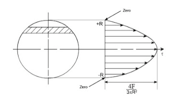
Stress resulting will be (4x0.5)/(3x3.14x0.25^2) = 3.4ksi/in (per above equation). How do I equate this to the thickness of the material? And could you share where the above equation comes from?
 
IMO, the critical shear plane occurs at the center of the circle along the diameter. Link
 
yup just realized that. Thanks

Going back to my earlier question, how to I equate the 3.4ksi/in to thickness of the material.

Can I say, stress at the 1" thick will be 3.4 ksi and hence the stress at 0.25" will be 13.6 ksi?

Is there a way to calculate the rupture based on AISC equations?

Just not able to come up with a procedure to calculate the base metal shear rupture strength for plug welds
 
BAGW:
Plug welds are suspect for real structural applications because they tend to be poorly made. Fusion with the base metal with the hole in it is usually not to good, penetration at the root is often not to good either, so you end up with a blob of weld fairly will fussed to the back-up base metal only. The access and range of motion required to make the weld properly needs special attention, which is usually not given to these welds. A longer, wider slot or a larger cut-out circle, with a fillet all around usually leads to a better weld, and weld detail. When analyzing the weld, the least strength comes from failure through the throat of the circumferential fillet, and you have some trouble rationalizing gaining much by filling the middle of the hole. This all assumes that you are using at least a matching weld metal and process, and its allowable shear stress, as compared with the base materials. These do not often fail or show flaws as relates to shearing the whole plug off, akin to the shearing of a pin or bolt. The other weld or base material checks are the leg of the fillet at the base metal, using essentially the allowable shear stress of the base metal, since weld puddle mixing is likely/suspect at the location. That is, the leg size, times its length for an area for the shear flow calc., using the lower base metal shear stress. This might apply when a fairly small fillet weld is applied to a thicker pl., with thickness greater than the leg dimension. Alternatively, the weld length, times the pl. thickness will apply to this same fillet weld when it is allied to a thinner pl., since the failure I more likely to occur in the pl. itself.
 
The thickness of the base material won't matter when checking failure of the base material. Area of the circle x ultimate strength of the steel. Failure of the base metal in block shear or similar would require the material thickness.
 
@ dhengr,

like we do thickness of the material x weld length for fillet weld to get shear area, can we do perimeter of the weld x base material thickness for the plug weld?

@ Canwesteng,

Why won’t the thickness of base material matter?
 
Typical failure mode of a plug weld is shear at the plane "inbetween" both plates. Plate thickness is irrelevant (unless really thin plates where you can have tear-out, but let's not go there).

 
A plug weld obviously has different modes of failure depending on the stress direction. Tension on a plug weld is not a good idea as the tension load does not engage the weld solution below the plug weld unless the perimeter shear area is large enough (with thickness of the top material being high enough to increase the shear area so that shear resistance is greater than the tension stress of the plug area). In most cases, the top material is relatively thin as compared to the base metal and the plug weld results in more of a clamping device than a weld failure mode.

The better mode of load resistance is in lateral shear between the two materials (as kingnero noted). In this case, all of the plug area needs to be mobilized for failure to occur.

 
The thickness of the base material affects capacity for other modes of failure, such as tear out. It doesn't affect failure at the base of the weld.
 
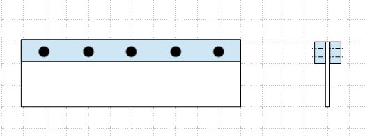
This is a hypothetic problem for discussion only. Assume the center bar (A) is to be strengthen by two upper bars (B), and the upper bars are connected to the center bar through plug weld. The complete section (C) can subject load of any kind. How to make it composite, and what to check? Please identify the "base metal".

image_o1smdp.png
 
Base metal is A. I would check shear flow at the show, plus the possibility of direct shear through the plug weld, assuming the load is placed on the outer bars. Those two loads would be additive via sum of squares. Then there is also block shear for the plugs tearing out of the holes, which may be a possible failure mode depending on how it is loaded. For any torsion I would just ignore the contribution of the B bars.
 
@ canwesteng, how to you check the direct shear through the plug weld? How do you satisfy the section J4.2 of AISC?
 
I am having a very hard time thinking of a situation where J4.2 would apply to members joined by a plug weld(s). That said, J4.1 and J4.3 would both need to be checked.

With weld design, by default, the fusion zone is at least as strong as the weld. This is based on the use of matching or undermatching filler metals (and is essentially what you are designing with a plug weld). So, when you are checking the base metal against (or per) J4, it is not a special check for the fusion zone, it is simply making sure your connected elements are adequate. If your plate is truly loaded in shear (remember, just because the weld is loaded in shear, that doesn't mean the connected parts are loaded in shear. i.e lapped plates loaded in tension connected with plug welds), you would be using the area of the plate that is resisting that shear, it is independent of the weld size. For plug welds, I would really only expect J4.3 (block shear) to have a meaningful check/impact provided the members being joined have already been sized appropriately for the given loads. Or, perhaps if you are plug welding one leg of an angle (or some similar situation), J4.1 may also control as shear lag would also kick into play.
 
Status
Not open for further replies.

Part and Inventory Search

Sponsor