Nick6781
Structural
- May 15, 2024
- 28
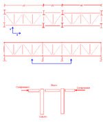
I'm designing something similar to the sketch below.
Under lateral load, the floor framing behaves like a truss, and I observe a significant amount of axial force in the chord members due to wind in the Y direction.
However, the chord is interrupted by interior columns, so it's not a continuous member.
If I'm using simple shear connections at the ends of all the beams, is there any issue with transferring the compression force through the middle beam (i.e., the middle segment of the chord)?
Since each simple shear connection can be idealized as a hinge, is there a concern with the compression force having to pass through two hinges before reaching the middle beam? Or will everything function correctly as long as the load path is properly designed and all members and connections are adequately detailed?

