Hello guys and gals,
I have several questions all relate to pneumatic devices on two unrelated equipment.
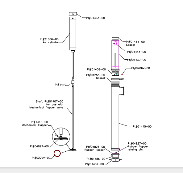
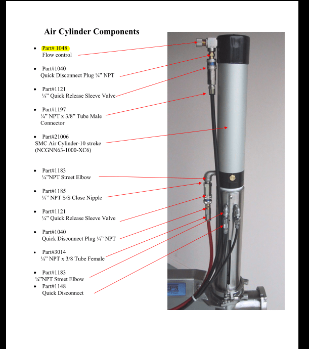
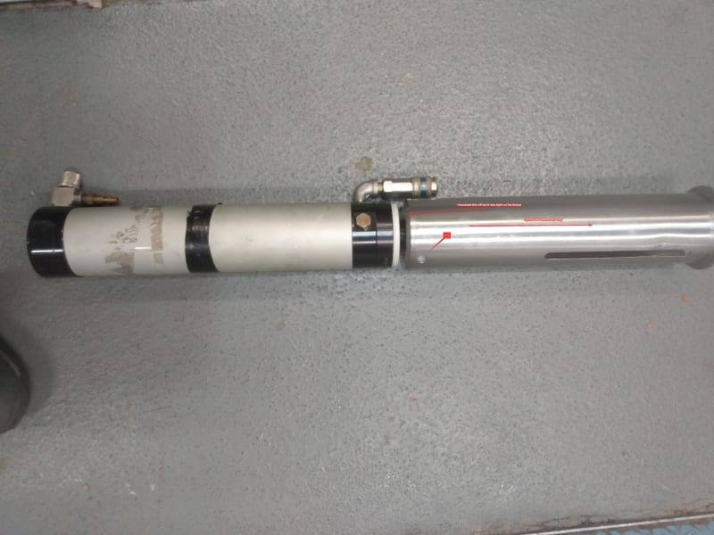
First. images number 1 and 2 are of double acting cylinder and a valve with something in front of it that I could not figure out, I believe the manual lists it as "threshold sensor", is this what is called end of stroke sensor and how does it operate?
The cylinder end has thread that goes into the end of a tube and it is pretty damn tight, the tube is stainless and inside it on that end looks like plastic (PTFE maybe) and there's a port in it. The port has a hose out of it that goes back to that box in image 2. The idea is that the cylinder would cycle back and forth none stop, it retracts all the was and somehow that hose going into that port makes it extend again. That is the problem, it does not extend.
So I disconnected the hose from the port and every time the cylinder retracts I momentarily block the hose end with my finger which would extend the cylinder and so on.
I hope that is enough information and hope someone explains to me how this part of the equipment functions?
I should mention that I removed the fitting on the port and put my ginger on it while the cylinder was moving back and forth and did not feel any pressure or vacuum, pretty much nothing.
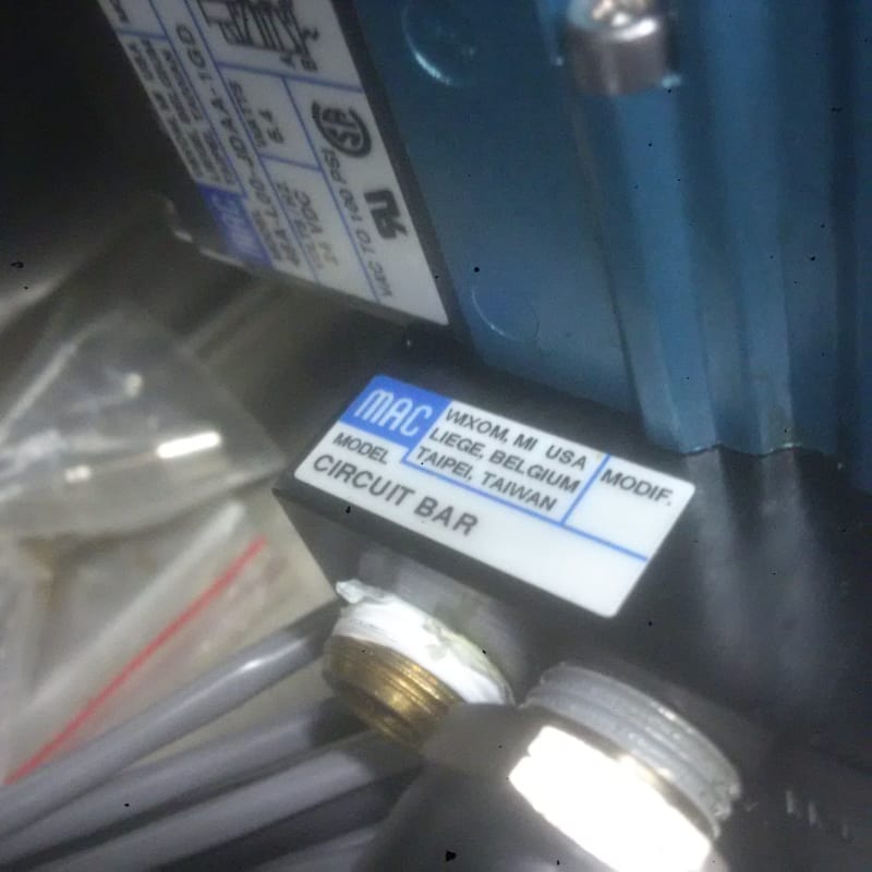
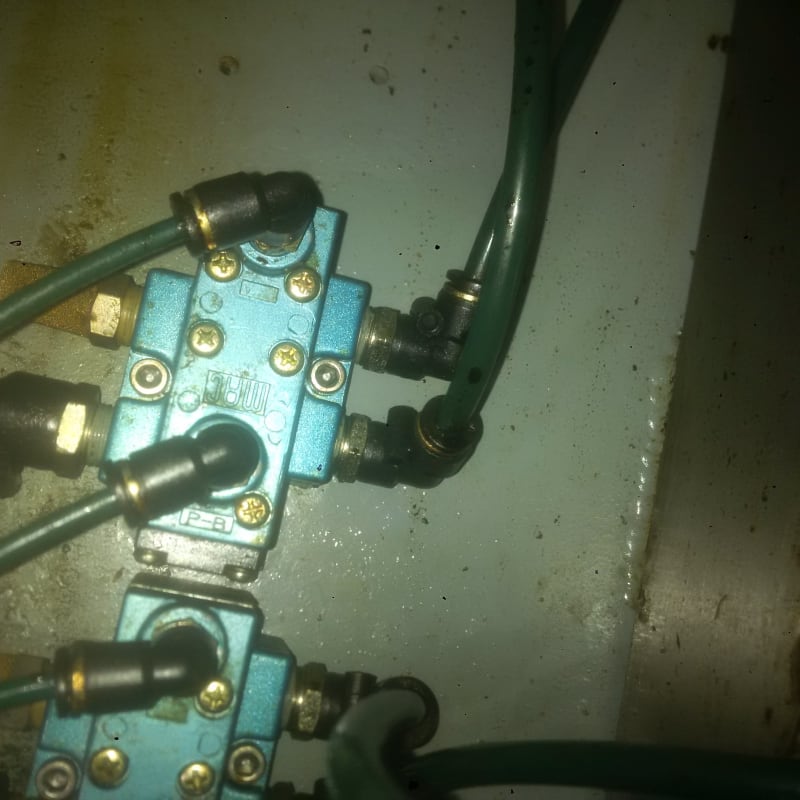
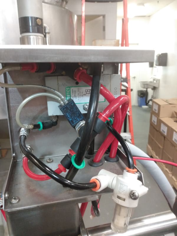
Images 3 and are in another machine and I would like to know what the function of a circuit bar and I am guessing image is of pilot operated valve.
I know very little pneumatics so anything will be helpful.
Thanks a lot
I have several questions all relate to pneumatic devices on two unrelated equipment.
First. images number 1 and 2 are of double acting cylinder and a valve with something in front of it that I could not figure out, I believe the manual lists it as "threshold sensor", is this what is called end of stroke sensor and how does it operate?
The cylinder end has thread that goes into the end of a tube and it is pretty damn tight, the tube is stainless and inside it on that end looks like plastic (PTFE maybe) and there's a port in it. The port has a hose out of it that goes back to that box in image 2. The idea is that the cylinder would cycle back and forth none stop, it retracts all the was and somehow that hose going into that port makes it extend again. That is the problem, it does not extend.
So I disconnected the hose from the port and every time the cylinder retracts I momentarily block the hose end with my finger which would extend the cylinder and so on.
I hope that is enough information and hope someone explains to me how this part of the equipment functions?
I should mention that I removed the fitting on the port and put my ginger on it while the cylinder was moving back and forth and did not feel any pressure or vacuum, pretty much nothing.
Images 3 and are in another machine and I would like to know what the function of a circuit bar and I am guessing image is of pilot operated valve.
I know very little pneumatics so anything will be helpful.
Thanks a lot