Eng-Tips is the largest engineering community on the Internet

Intelligent Work Forums for Engineering Professionals

  • Congratulations waross on being selected by the Tek-Tips community for having the most helpful posts in the forums last week. Way to Go!

Point loads on a blind flange 3

Status
Not open for further replies.

Plungeman

Mechanical
Apr 6, 2022
7
0
0
GB
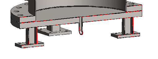
I'm working on a pressure vessel with a blind flange at its base, supported by a few large SHS's. To avoid FEA, can anyone direct me to a suitable hand-calc that could be used to assess the effect of the legs on the flange?

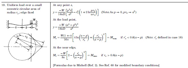
I'd been thinking of using Case 19 from Table 11.2 in Roarks 7th edition, to compare the deformation due to the reaction force from the legs to the magnitude of deformation from internal pressure, but despite it being for a fixed edge the results I'm getting have deformation at the perimeter - clearly something's not right there, and I'm struggling to find another resource.
 
Replies continue below

Recommended for you

Helpfully my reply to @r6155 didn't publish...

To work with some round numbers, as I'm now away from the data:
[ul]
[li]DN600 PN6 Flange at the base of a vertical pressure vessel[/li]
[li]3barg applied internally[/li]
[li]4x 50x50x3mm SHS's (Square Hollow Sections - aka box section) equispaced on a 500mm PCD[/li]
[li]1000kg fabrication mass (acting as a line load at 600mm DIA)[/li]
[li]500kg fluid mass (acting as a UDL on the inside of the flange)[/li]
[/ul]

The critical point in this instance is the effect the legs have, as the integrity of the flange itself is verified easily by other means.

For information, this is the Roark's case that seemed to suit best (however deflection at the edges would suggest the formulae aren't right for the fixed edge case):

08.04.2022_09.04.35_REC_wlwdhm.png
 
@ Plungeman
See Pressure Vessel Design Handbook, by Bednar.
Pressure Vessel Design Manual, by D. Moss. .......and others

Regards
 
@ r6155

Both new documents to me (I've recently moved out of API 6A & ASME BPVC.VIII.Div2 to free-standing, low pressure vessels) with a wealth of information. Had you a specific section in mind in either of those, or am I looking at a fun weekend of parsing out the applicable components for the situation I have?

Image of the base of the vessel (I feel the need to point out that I'm being asked to verify by 3rd party, as there's 64mm of steel directly above the legs...)

08.04.2022_16.11.16_REC_agonhx.png
 
IMO, the typical concepts of the pressure vessel design may apply to either high or low pressure condition.
Just curious what the service this low pressure vessel is applied to, as it's a bottom flange cover design.
 
Bednar's book and Moss's book would not cover such a situation as that is a highly unusual design. In fact I doubt that any Pressure Vessel book would cover this topic. Barring FEA analysis, Roark's book would probably be your best bet since it's not intended for pressure vessels exclusively.


-Christine
 
All PV manuals are useful for unusual or unpopular designs, but there are people who don't know how to use them, nor the codes and standards. They look for the same figure that they are presented with and since they cannot find it, they say that this PV manual is useless.

Regards
 
r6155, read for comprehension. Nothing in the Bednar's book or Moss's book covers this particular topic. They're useful handbooks but they are completely irrelevant to the topic at hand.


-Christine
 
Would it be feasible to make those legs into a circular skirt, so the blind flange can then be analyzed by circular-plate formulas from Roark?
 
@ Plungeman
For lugs supports Bednar is clear. The effect of lugs in the blind flange see "Support Lugs with Full Backing Rings" (by Bednar) for guidance and use appropriately.
NOTE: This design is not a good idea, avoid welding on blind flanges. PWHT or preheat may be required depending on material.

Regards
 
Problem is, if you apply ASME design rules to a standard flange the flange may fail even before adding the legs.

The legs are in line with the gasket face so are not putting bending loads into the flange (from gravity anyway). Could be OK. Compare the stress in the flange due to pressure and bolt up with the stress from compression in the legs. Bending in the legs from EQ could high.
 
@ KevingNZ
Yes, you are on the right way.
I just thought that the diameter of the circle of the legs is in line with the mean diameter of the shell.

Regards
 
KevinNZ,

You may attach 2 parallel plate stiffeners on to the blind flange for opposite legs, another two for other opposite legs. This may help providing stiffness against deflection under pressure in addition to creating support on blind flange for legs (you may weld support legs on to the stiffeners on each side). You may increase the number of the stiffeners in case you want uniform correction all around which may help correcting the uniform pressure on the sealing gasket. I hope my description clear, I cannot draw and attach a sketch at the moment.

In case the welding at around the centre of blind flange you may add a pipe which will have the same height of stiffeners. This may help for the access of the drain pipe. Just be careful with the nozzle access.

Of course you need to make some structural calculation on the stiffeners for the proper load path and stress distribution on them. Ultimately you may try FEA.

Beside all, I have to ask why you are using a blind flange instead of a head. Blind flange draining at centre will not warrant full drainage, and cause corrosion.

Regards.
 
I am looking at your problem differently. You will have two types of deflection and stresses which can be superimposed for a final answer. One type of deflection will be caused by the internal pressure within the vessel and the second type of deflection will be caused by the weight of the vessel.
Imagine the vessel to lay on its side, you'll realize that the blind flange is uniformly supported at its edge by the bolt pattern and the deflection curve on the blind flange will be solely from the internal pressure in the vessel from which stresses can be determine.
As far as the weight on the vessel on the supporting legs you will have four opposite point loads on the blind flange from the legs. the load on the legs is due to the uniform load created by the vessel flange near the edge of the blind flange. Another deflection curve will develop from such reactions. The two deflection curves and resulting stresses can be additive.
Equations for deflection and the resulting stresses can be viewed in Kent Mechanical Engineering handbook "Design and Production" 12th edition pg 8-32 thru 8-35. The drawings and formulae presented by Kent is by permission from Formulae for stress and strains 2nd Ed., by R.J.Roak copyrighted 1943.
 
Status
Not open for further replies.
Back
Top