Continue to Site

Eng-Tips is the largest engineering community on the Internet

Intelligent Work Forums for Engineering Professionals

  • Congratulations waross on being selected by the Eng-Tips community for having the most helpful posts in the forums last week. Way to Go!

Point loads on CFS steel studs 1

Status
Not open for further replies.

canadiancastor

Structural
Apr 13, 2014
34
I have a project where we are using an aluminum substructure to attach granite panels (rainscreen building enveloppe). The aluminum substructure is attached to the building stud wall, which has studs at 16" O.C. and spans concrete slab to concrete slab. The substructure is attached with local aluminum angles at every 32" O.C. horizontally and at every 39" O.C. vertically. All of the dead load of the system and of the granite panels is transferred at every concrete slab (they substructure is "hung" off the slab face), so the steel studs only serve as a backing to resist wind loads. The criteria used for the maximum deflexion of the studs is H/600.

The stud wall sub-contractor did not take into account that we had clips a 32" o.c. and designed his wall for the standard wind loads. I am suggesting to simply double every stud, that way even if we don't know exactly which stud will be loaded, it will be able to withstand twice the load, which is the loading if we have clips @ 32" o.c.. There is the issue where the studs is also point loaded vertically, but I ran an analysis with the exact spacing of the loads, and using a distributed vertical load is conservative.

His engineer does not accept the solution I proposed above. He says that we cannot simply load half of the studs. If one stud deflects to L/600 and the next stud does not deflect, there will be a large difference between the deflection of adjacent two adjacent studs. Is this a valid point? I'm thinking maybe, but at the same time I used built-up wood studs to resist a point loads on many occasions without issue? There is a gypsum sheeting on each side of his stud wall, does that distribute the load over 16"?
 
Replies continue below

Recommended for you

Sounds like that cladding system was designed for an Aluminium Million rather than CFS. You can technically do it the way you describing however meeting the deflection will likely be a struggle as you your deflection length is now also between studs? So ~400mm in length (like 1.6mm of a limit). You could try cross strapping between studs (weaving a strap between studs) to try and 'link' studs.
 
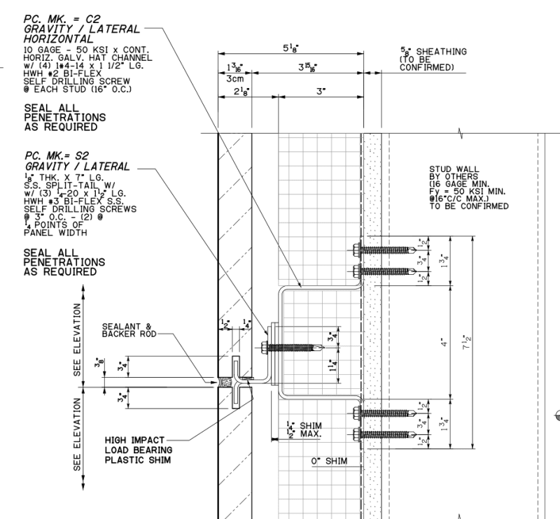
We provide engineering for exterior stone on light gage studs regularly, and this is often a problem. We typically use a continuous horizontal element (hat channel or light gage track) outside of the sheathing that is installed first, and anchored to the studs at 16"c/c. This horizontal element helps distribute the load over multiple studs, plus eliminates the need to coordinate the substructure anchor locations to the stud locations, which we have found to be a real challenge in the past, as these components are typically designed and installed by two different designers/contractors. Plus, we find that the pullout of the screws into the light gage typically controls, and adding the horizontal member can allow for additional screws if needed. Unfortunately, in my experience, I find that the light gage designers don't typically consider (or have access to the relevant information) on how the cladding will be attached. One additional heads up, while this approach has worked for us for years, though we have recently found on more jobs that this can be an issue thermally, based on the new attention to building thermal performance.

Hope this helps
 
another thought - have you considered coordinated differential movement for vertical deflections?

guessing the steel stud has a slip-track at the head to allow slab deflection over not to crush the steel studs. but if the cladding is hung from the slab, and also anchored back to the wall, wont the cladding and the steel studs be pinching eachother if there is vertical slab deflection to accommodate?
 
@mgmc If we need to check the H/600 between two studs, that would never work. It follows that it's impossible to have anything point loading a single studs in a wall, since it will deflect more than it's neighboor, which I find odd.

@jjl317 You are right on. I was looking into using uni-struts as a horizontal reinforcement, but a rail could be even better considering we need to put rockwool insulation in the same cavity. I ran some calculations and it appears that we could put a couple of rails on the studs to help distribute the loads, even if they aren't "behind" the clips. Do you always put anchors on the horizontal element? This would be a bit problematic for our sequence of installation.

@NotthCivil Everything that is tied into the studs has a rail that provides free up and down mouvement, it's designed into the aluminium substructure. We have a an expansion joint at every story to take the slab movement.
 
The bulk of our work utilizes individual anchors, which we attach directly into the horizontal element. For deeper cavities, we will use a hat channel, as it reduces the structural needs for the anchor itself, plus can coordinate the geometry to match the insulation (i.e. 3" horizontal projection on the hat channel coupled with 3" insulation), to simplify install (see sample below). However, when we use a proprietary framing system, the locations of the horizontal framing members often vary vertically, depending on the capacities of the various components.

sample_hat_channel_detail_dd5quh.png
 
Status
Not open for further replies.

Part and Inventory Search

Sponsor