Continue to Site

Eng-Tips is the largest engineering community on the Internet

Intelligent Work Forums for Engineering Professionals

  • Congratulations KootK on being selected by the Eng-Tips community for having the most helpful posts in the forums last week. Way to Go!

Point Mapping Algorithms

Status
Not open for further replies.

sticksandtriangles

Structural
Apr 7, 2015
472
I am on the hunt for mapping algorithms to link structural engineering software beams and columns to revit beams and columns.

The problem:

Often our revit models and engineering models are located at differing points in global space and maybe even rotated. I want to be to map the two models together with some form of a tolerance.

See image below:
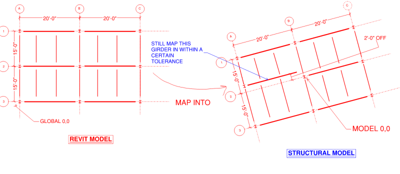
Beam_Mapping_Algorithm_hptnx9.png


I have written some sloppy code previously to tackle this problem, but it requires manual input for mapping the global coordinates between the two programs and could not handle a rotation type parameter.

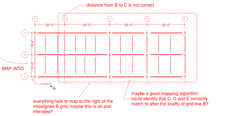
Also, if one of the gridlines gets significantly off (say 3'-0" or more), the sloppy mapping algorithm falls apart and flags all other elements as being out of sync. Maybe a good mapping algorithm could tackle this, flagging the offending bay, and then mapping correctly the remaining bays beyond?
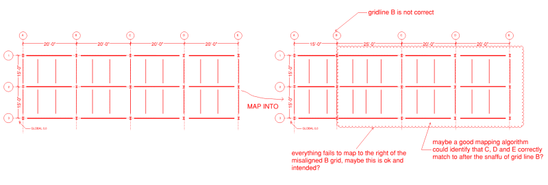
issues_with_mapping_xbvntw.png


Anyways, the end goal is to map beam and columns from one piece of software to another, with a robust mapping algorithm.

I am fine with sticking with 2d if need be, but the end goal would like be a full 3d solution. Assume that all grid line locations are known between the two pieces of software and all beam/column coordinates are known.
Are there any famous algorithms for mapping points between one "system" to another "system"
 
Replies continue below

Recommended for you

Are these actual points, ala point clouds, or are they proprietary structures?

assuming point clouds, it sounds like you want to do this
possibly this
TTFN (ta ta for now)
I can do absolutely anything. I'm an expert! faq731-376 forum1529 Entire Forum list
 
These are not point cloud "points", these are "points" that represent beam and column ends. Sorry for the grainy images before, the images should be more clear now with text.

The Point Set registration stuff is pretty interesting, might be the ticket.

S&T -
 
these are "points" that represent beam and column ends.

Not sure that matters, since the set of points is a point cloud, and you'd have to extract them from each program anyway, if you wanted to correlate them

TTFN (ta ta for now)
I can do absolutely anything. I'm an expert! faq731-376 forum1529 Entire Forum list
 
You can construct a transformation matrix for the desired new location. Each point in the original model can be multiplied by the matrix to get the new coordinates. You will find a lot of resources online if you search for "transformation matrix", "point coordinate transform", or similar terms.

I'd be surprised if numpy doesn't have something useful for this situation.
 
quick thought is you should be able to accomplish it as long as you know two anchor points:

Use one of the two anchor points to determine the required x,y translation then use the other anchor point to determine the required rotation. Use this information to determine the transformation matrix to then apply to the other points.
 
Oh I think I get what you want to accomplish:

1. determine two anchor points between the structural model and revit model (probably needs to be a manual entry)
2. determine transformation matrix to go from the structural model to the revit model
3. apply transformation matrix to the structural model data
4. Map structural columns to revit columns, during this procedure allow for a radius of tolerance. Log elements without a match ie poor model coordination

After transformation matrix applied:
matched_cols = []
matched_beams = []
tolerance = 1

for rcolumn in revit_columns:
for i, scolumn in enumerate(amodel_columns):
if vector_distance(scolumn, rcolumn) <= tolerance:
matched_cols.append(scolumn)
amodel_columns.pop(i) # remove the matched column from the list, speed up each inner loop cycle

#anything left in the amodel_columns list is an orphaned element

for rbeam in revit_beams:
for i, sbeam in enumerate(amodel_beams):
idelta = vector_distance(sbeam[0],rbeam[0])
jdelta = vector_distance(sbeam[1],rbeam[1])

if idelta <= tolerance and jdelta <=tolerance:
matched_beams.append(sbeam)
amodel_beams.pop(i)

#anything left in the amodel_beams list is an orphaned element
 
Celt,

You have the process really well locked down.
The code you have outlined I currently have written up and what I have deemed as "sloppy".

Currently I have to manually perform steps 1-3, I think I can get this automated.

Step 4 is the part where I was hoping to come up with a better algorithm. My system works exactly as you have outlined, checking if start and end nodes are within a defined radius tolerance, then the beam is mapped

This system falls apart in the second example I posted though, with the bays beyond the misaligned grid line all not mapping. Maybe this is intended? If I could get a more robust algorithm to match grids C-E that would be awesome, but probably a much more in depth solution.

Posted again for reference:
Original Space

beam1_f3t4y7.png


Mapping Space - B to C gains 5'-0" from the original space, causing for a flag of all beams beyond column line C
beam2_rlachk.png


Thanks Cowski, I think that transformation and coordinate side should be pretty easy to handle, the biggest part of this is trying to come up with a robust mapping algorithm.

S&T -
 
yeah that wouldn't match in my approach because the structural model and Revit model are off entirely by 5ft horizontally beginning at grid B.
If this was a simple modeling error where grid line B was just shifted such that A-B was 15 ft and then B-C was 20 ft then it would work because C-E would be in the right relative locations, but what your screenshots show is a complete lack of coordination between the design and drafting models.
 
For modeling discrepancies of that magnitude I don't think mapping is the way to go as the coordinates won't really every match up. This is where you'd need some kind of unique identifier and a database to keep track of the elements (if I recall this is what a lot of analysis software -> Revit links are doing to manipulate element positions bidirectionally).
 
Celt83 said:
what your screenshots show is a complete lack of coordination between the design and drafting models.

That's a good point, I think something like a grid line misalignment should be flagged pretty frequently. I worry about larger buildings slowly accumulating 6" of deltas over 20 times to the point where it no longer maps.

Of note, I think complete lack of coordination between design and drafting models happens way more than we like to admit. I am hoping this tool can solve this. I know many times where I have been up around 10'-0" misaligned with the drafting model and because the general shapes match between engineering and drafting model, it masks the problem.

Maybe the "sloppy" code is best approach and this is easier than what I originally had thought.

S&T -
 
For the most robust system with arbitrary misses outside of say 10%(ACI 318-19 6.6.4.2) I think you'd need to rely on matched element ID's and not coordinate positions.
 
I'll try out a few options and see which one works out better, I think the more advanced mechanisms may still be of value. Maybe a user option on mapping algorithms.

S&T -
 
Ok, so the alternative is 3 translations and 3 rotations, i.e., 6 unknowns, so if you have more than 6 points and they are exactly matched, you will find a solution that maps exactly. If they don't match exactly, then the two structures are not identical, but the coordinate transformation will be close enough for you to see what's not matching.

{edit] plus magnifications, I guess, so possibly 3 additional unknowns, unless there's just a global magnification

TTFN (ta ta for now)
I can do absolutely anything. I'm an expert! faq731-376 forum1529 Entire Forum list
 
What’s the end goal here map analysis to documentation and transfer key results to Revit family parameters ( beam end reactions, column base reactions, etc.) or are you looking to do actual geometric manipulation to either the analysis or documentation model to bring them in line?
 
IRstuff said:
Ok, so the alternative is 3 translations and 3 rotations, i.e., 6 unknowns,

Yep, youve got it, I think we can eliminate (2) of the rotational parameters, I think the only realistic rotational parameter I will have is about vertical Z axis. I do not expect to have to deal with rotation about X or Y.

Celt said:
What’s the end goal here

Main goal is a QA/QC checker for our analysis models and our drafting models.

Ideally it can flag big discrepencies in beam/column locations and then also flag if the beam size/any other parameter does not match between the two pieces of software.

Whole model manipulation is not the goal at this time.

S&T -
 
OK, so 3 translations, rotation about Z, and a single scaling? That's something that could be dumped into a least-squares solver. Then, each point can be checked for coincidence after transformation. If they don't match, then something is off in one of the two models. That's something I think students do in computer science classes, particular in either image processing or computer game programming

TTFN (ta ta for now)
I can do absolutely anything. I'm an expert! faq731-376 forum1529 Entire Forum list
 
To 'diff' an analysis model with a production model as a form of QA/QC, I recommend using grasshopper with the BHoM library
The BHoM library will allow you to database the elements of your respective models (as well as grid locations) and grasshopper components can be used to perform the comparison calculations which can be as simple as the distance formula between endpoints or midpoints or both. Where distances exceed some allowable tolerance, these members can be flagged in Revit model as a color override with further libaries (RhinoInside).

[]
 
Thanks for the info e95kwon, I have seen the BHoM library before, but haven't used it.
We do not have rhino/grasshopper at our office so this won't not work for me.

There's also no fun in using a prebaked system! It should be an interesting coding exercise.


S&T -
 
Status
Not open for further replies.

Part and Inventory Search

Sponsor