Eng-Tips is the largest engineering community on the Internet

Intelligent Work Forums for Engineering Professionals

  • Congratulations waross on being selected by the Eng-Tips community for having the most helpful posts in the forums last week. Way to Go!

Point Reactions

Status
Not open for further replies.

TTCorona132

Mechanical
Mar 28, 2016
15
AU
Hi all!

Apologies if this is in the wrong spot as I am new here.

This also may seem pretty basic problem, but there is some argument about it going on in my office so I wanted to see what others thought.

Below are two scenarios.
Basically just looking for the reactions at A, B, C and D
All loads shown are acting into the page.
The reaction points are rollers that can roll towards the AB end or the CD end
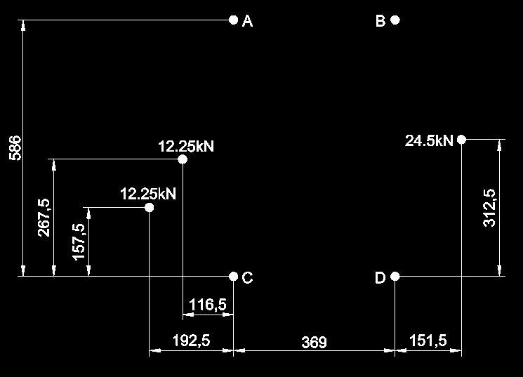
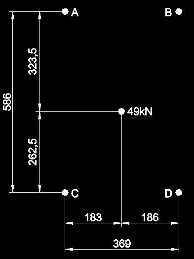
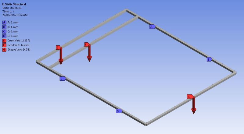
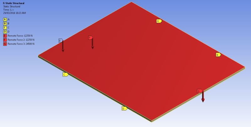
multi_hwqjie.jpg

Single_ols1lt.jpg


Look forward to you help
any tips pointers about the problems or the forum please let me know

Thanks
Mat
 
Replies continue below

Recommended for you

"So the load at the centroid position is attached to the individual load points via a steel wire rope." ... what the heck does that mean ? no-one has said anything about a rope before ? the way the problem was represented the load at the centroid is a theoretic equivalent for the set of applied loads. the solution should be the same for the set of loads and for the load at the centroid (of the loads). the external loads should eb the same, the internal loads will be very different (can't use a centroid load for internal loads)

another day in paradise, or is paradise one day closer ?
 
So if I treat it as 5 beams then I get this scenario
beams_osxmnp.jpg


A = 7.66kN
B = 14.29kN
C = 17.04kN
D = 10.01kN

Much the same as my calcs above..

If I treat it as a solid box
plate_g6tyft.jpg


A = 11.51kN
B = 11.08kN
C = 13.99kN
D = 13.00kN

which are much the same as using the centroid..
 
Sorry.. no rat here... just a little clueless hahaha

So my actual structure is represented by the beam model shown above,
then these are the results of my reaction loads I should be using?

And not simplifying it to a "rigid black box"
 
A "rigid black box" is indeterminate when there are four supports. The solution requires a knowledge of stiffness of the box. The black box structure is determinate with only three supports. You can say, however that the centroid of the applied forces and the centroid of the reactions are identical.

The simple span beam structure is determinate and all four supports are required for stability.

BA
 
i have to admit that i'm surprised that the centroid solution is so different to the "grillage" solution ... why do the models have different couples in the reactions ??

no surprise that the grillage model matches the hand calc (it's determinate).
is there a moment reaction included in the black box model ?

as an exercise can you run those two models for each load separately

another day in paradise, or is paradise one day closer ?
 
We are also a bit surprised by the answer which is where this discussion has come from.

I'm not sure what you mean by "why do the models have different couples in the reactions ??"

there are no applied moments added to either model..
only the loads and supports shown..
the supports are what Ansys calls "Simply Supported" in which they can pivot in any axis, but they cannot translate.

I have run the load results separately previously on the beam model in Ansys, and I get the same results as when I manually calculate each load separately.
 
I think that treating the solution as a plate/box means the loads can propagate through the plate to each support evenly.

Where as within the actual structure of the product, when represented by a beam model,
the loads have discrete paths that they need to take and as such will load up particular supports more than others.
 
TTCorona said:
I think that treating the solution as a plate/box means the loads can propagate through the plate to each support evenly.

What does that mean? The problem is indeterminate, so the calculation is invalid. It cannot be solved by statics alone.

Consider the 49kN load located as shown. Take moments about AD. The eccentricity of load from diagonal AD is about 16 mm toward C, practically on diagonal AD. If support B is removed, support A takes 262.5/586 * 49 = 21.95 kN and supports C and D together take 27.05 kN with C taking only 2.51 kN and D carrying 24.54 kN.

Alternatively, consider moments about diagonal BC and nearly all of the load is carried by supports B and C.

The correct analysis must take into account the stiffness of the box.

BA
 
What if we assume that both the plate and the beams used in both methods are infinitely stiff?

 
I am just looking at it as a free body diagram so no member strength/stiffness has been added at this stage
 
TTCorona said:
What if we assume that both the plate and the beams used in both methods are infinitely stiff?

The beams are statically determinate. No matter how stiff they are, the answer is the same. If the supports are not precisely at the same elevation, the answer is the same.

The infinitely stiff plate is statically indeterminate to the first degree because there is one redundant reaction. If one of the supports is a hair's width higher or lower than the other three, the load is carried by three supports.

We have all sat at a wobbly table in a restaurant where one leg is shorter than the others. Lean on it one way and the short leg takes load. Lean on it another way and the diagonally opposite leg takes load. If leg A is shorter than the rest and the load is centered, the entire load is carried by B and C.

In the real world, we do not have infinitely stiff members and we do not have supports which are built precisely at the same elevation and even if they were, we cannot be certain there will not be differential settlement.

From statics, A+B, C+D, A+C, B+D, B+C and A+D can be determined but individual values for A, B, C and D cannot be determined without considering compatible deformations of the black box and the four supports.


BA
 
Status
Not open for further replies.

Part and Inventory Search

Sponsor

Back
Top