Continue to Site

Eng-Tips is the largest engineering community on the Internet

Intelligent Work Forums for Engineering Professionals

  • Congratulations SDETERS on being selected by the Eng-Tips community for having the most helpful posts in the forums last week. Way to Go!

Polyworks problem

Status
Not open for further replies.

Alan Lowbands

Aerospace
May 17, 2017
274
Hi guys,

I was hoping someone will be able to help with a problem with a polyworks report.

It was created from a scan and reports the positions of 4 lifting attachments.
The problem is it's reporting the position and diameter symbols but including an S symbol.
I assume this is spherical symbol but not sure why it's there.

If anyone can help it would be really appreciated.

thanks
Al
 
Replies continue below

Recommended for you

Could you show how/where it's shown?
A circled S also used to be a modifier for Regardless Feature Size in older versions of ASME/ANSI Y14.5.
 
Sussed out how to put it on :)


Capture1_qfjqnw.jpg
 
Alan,

I would say that the S is for spherical diameter. In ASME Y14.5, a Position tolerance applied to a spherical feature controls the center point in a spherical tolerance zone and the callouts would look like the ones in the report. Whether or not the lifting attachment positions required this is a different question - usually there are X, Y, and Z deviations reported and not just X and Z.

Evan Janeshewski

Axymetrix Quality Engineering Inc.
 
thanks Axym.

The z position wasn't required.
We just needed to be sure the x & y positions fell within the 5mm diameter tolerance.
This is the first report I've had from a laser scan, could it be something to do with how the software interprets the point cloud?
I'm totally guessing but there was no option to remove it in the software.

 
How odd - 2*sqrt(.889^2 +.243^2)= 1.843...

I wonder where 1.822 came from.
 
What is the shape of the lifting attachments being checked?
 
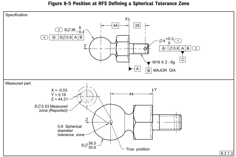
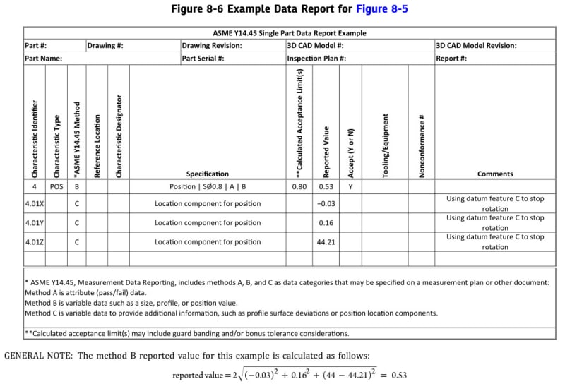
The measured value is the diameter of a spherical location, pls see Figure 8-5 and 8-6 of ASME Y14.45 Measutement Data Reporting as shown below.

2022-11-28-1_jzwq3u.jpg

2022-11-28-2_s5nve9.jpg


Season
 
If the 2D deviation is larger than the reported 3D deviation then only an imaginary component can be vectorially added to the 2D deviation to make it smaller.

Since that example in Figure 8-5 is rotationally symmetric, how does one know which orientation of datum feature C is being used? The part could be rotated which would flip the signs of the X and Y components.
 
3DDave,
Since the part is rotationally symmetric, the exact orientation of datum feature C around datum axis B doesn't matter. If the machinist has to adjust the process, he needs only to correct the total offset (which can be found from the X and Y components regardless of their signs) of the center of the sphere from the datum axis B. The direction is meaningful only for the distance from datum plane A along Z.
 
It matters for the purpose of the report. If the machinist makes a correction based on the wrong orientation from flipping X and Y the error will be doubled on the next part.

Thanks for your comment. Keep helping.
 
A decent machinist won't make a "correction" that increases the offset between features with nominally coincident centers.
You're welcome.
 
He's told what direction the offset is in in the report - that's why the report is made. If the machinist knew which way the error was it would have been corrected already.

I suggest a trip out to the shop floor a few times a year. You might learn things.
 
That's like trying to correct a coaxiality error of a part that is turned on a lathe by considering the signs of reported axis offset components in the X and Y directions. Makes no sense.
 
Cheers guys.

I know the positional results are wrong, that's what I'm trying to get to the bottom off.

The features reported are just cylinders, what I'm trying to find out is why they are being reported spherically.
I think it's more of a software question.

regards
Alan
 
Alan,
I can't answer regarding what the software does, but in principle, the shape of the tolerance zone depends on how it's called out in the Feature Control Frame (I think "Tolerance Frame" in ISO GPS or BS). As you probably know, for a cylinder, usually there is the 'Ø' symbol preceding the tolerance value, and then the tolerance zone is a cylinder. If there is no 'Ø' before the tolerance value, it is either intended to be a two-parallel-planes tolerance zone in which the axis must fit (rare but supported, at least per ASME Y14.5), or more likely - someone forgot to place the symbol. I would say that 'SØ' for a tolerance that controls a cylindrical feature makes no sense at all because you don't require the feature axis to fit within a spherical zone. You must be correct - definitely seems like a software issue.
 
I've encountered a few cases where a designer was intentionally creating a spherical tolerance zone for a cylindrical hole, but the intent was to just measure a point at the end of the axis (where the hole intersects with the datum plane for the part).
That is a terrible idea, of course, but that was what they were attempting to communicate.

John-Paul Belanger
Certified Sr. GD&T Professional
Geometric Learning Systems
 
Hi Burunduk,

The result contains the position symbol followed by SØ. (sorry cant get the position symbol to type in on here)
If you scroll up I've pasted a screen shot.
It's a weird one, none of the results add up.

thanks
Al
 
Status
Not open for further replies.

Part and Inventory Search

Sponsor