Continue to Site

Eng-Tips is the largest engineering community on the Internet

Intelligent Work Forums for Engineering Professionals

  • Congratulations SSS148 on being selected by the Eng-Tips community for having the most helpful posts in the forums last week. Way to Go!

portal frame gable end wind load analysis 1

Status
Not open for further replies.

wrxsti

Structural
Sep 18, 2020
196
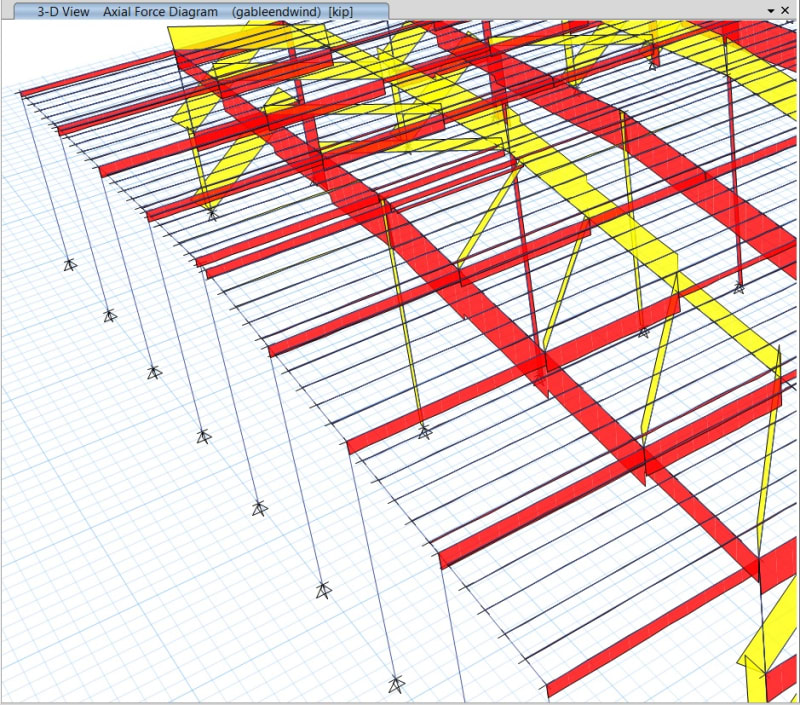
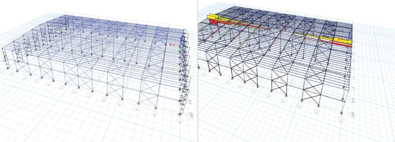
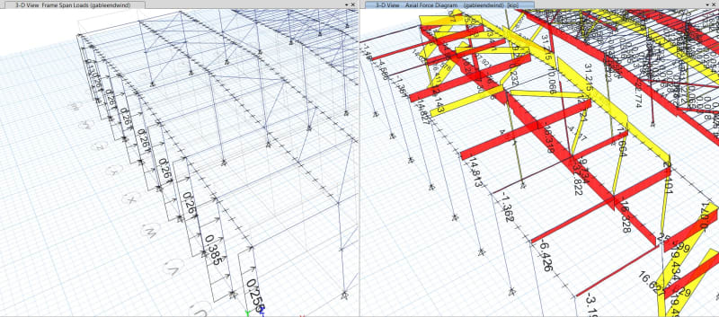
hi, im getting this high axial load at the center of propped portal
causing my rafters to fail in minor bending

see image

any ideas?

april28th_dkzilv.jpg
 
Replies continue below

Recommended for you

looks like software auto end length offset
 
How come your moment diagrams (point load) don't match your shear diagrams (uniform)? Are they the same load case?

How about we run it removing all of the purlins except these ones:

1) Those that align with truss panel points and;

2) Those that align with column tops.

It's often a good strategy in this situations to strip out that which may be extraneous.
 
yeah im not sure why the moment diagram is not parabolic but the max moment works out
 
Maybe this is software that needs the columns subdivided into several elements?

You have to be careful with offsets and releases. If you have offset the column to the rafter bottom flange, you'll be putting a twist into the rafter. In reality, you need stiffeners to get the load up to the truss level.

Is it stable? These braced bays don't look healthy.

Screenshot_20210430-074756_Samsung_Internet_vdz1h5.jpg
 
values through strut still seem high

11_april29th_no2odd.jpg


if you consider the points loads they should be
12_april29th_nauvo1.jpg
 
@steveh49 yea that deflected shape was from auto-meshing with frame intersects which i turned off
and deflected without that option looks more like the last post above


im just trying to get an idea of how much minor bending will occur in the rafters but as you can
see with these excessive axial loads being generated saying my Syy needs to be 3x what it is right now
which i dont think? is really required looking on similar portal frame buildings


So we'd expect the axial in that piece to basically just be the incoming reaction at the wind post there, right? What is that value done by hand? What's the value that your model is providing?
 
i havent done the truss part by hand but the point load from the gable end column at the ridge should be about 9 kips into that strut

but the program is telling me 209 kips [sad]

its doing something weird where the strut is in compression should be in tension and the immediate members around it are the ones in tension


april30th_qkldjc.jpg
 
ok so i zeroed all frame offsets on all the members
took off autoframe meshing at frame intersection

and im getting back some ok results see below

what do you guys think?

2_april30th_dzlkun.jpg
 
Why do you have your in plan roof bracing spread throughout the roof and concentrated more in the centre? I see this often in what seems like computer generated portals. With this setup you either are not utilising the centre bracing or you are allowing significant lateral forces to be carried through the roof across several bays. In many cases this is a convoluted and not an efficient load path given that the majority of the lateral load occurs on the end bays.

You don't seem to have a load path from the end bays to the internal trusses beyond the secondary rafters (purlins?). Have a clear load path from the wall to the ground. It doesn't seem like you have thought this through. More like just put together a model and let the computer spit out answers. Decide on your load path and design it in.
 
human909 yea its a model im checking for someone i havent gotten to that part yet
i was trying to resolve the transfer from gable ends to the roof truss system
i will probably remove one of those middle truss bays
but more than likely carry down the force before then

thanks for the input, appreciated
 
wrxsti said:
human909 yea its a model im checking for someone i havent gotten to that part yet
Fair enough.

I'm not sure if my rely came off as blunt, but I kinda had that tone in my head. Portal frames with bizarre load path have started to get me both annoyed and puzzled.
-Annoyed because I've seen failures in distant past due to no discernible load path.
-Annoyed because I've currently been dealing with a D&B supplier who is designing similar portals
-Puzzled because if such designs are quite common, maybe it is ME who is missing something.....

The few portal frame buildings I've designed tend to have minimal or no bracing in the roof/walls except for at the ends. The logic being that is where most of the lateral load is. There are a few drawbacks such as concentrating shear and uplift at the ends and potentially thermal expansion but overall I don't see these as being significant. That said I've designed a handful of these type of structures, I'd presume those who do it for a living would have an economical design nailed down well.
 
If you auto-generate loads and have no girts modeled, maybe the loads to the roof are not coming up through the columns, but rather they are being applied directly to the rake beam. This would explain the weird column loading and the large loads on the rake.

I don’t like auto-generated loads and I don’t like dealing with a model someone else started.

Dump this model and make your own. You have spent more time trying to figure this out than it would take to start from scratch.
 
Status
Not open for further replies.

Part and Inventory Search

Sponsor