Continue to Site

Eng-Tips is the largest engineering community on the Internet

Intelligent Work Forums for Engineering Professionals

  • Congratulations cowski on being selected by the Eng-Tips community for having the most helpful posts in the forums last week. Way to Go!

Portal frame rafter LTB 1

Status
Not open for further replies.

johannes17

Structural
Jul 23, 2015
6
Hi all

This question is similar to a previous one of mine, but with some difference.

I am designing a standard steel portal frame (elastic analysis) with the following details:
1. Total clear span = 12m (duo pitch portal with 15 degree roof slope)
2. Haunches at the eaves and apex (ex IPE 180 AA sections with lengths = 10% of total span);
3. No kneebracing has been used (to reduce fabrication and erection time)
4. Purlins spaced at 1.5m along slope (100x50x20x2mm CFLC);
5. Rafters = IPE 180 AA
6. Columns = IPE 180 AA

How would I determine the rafter's effective length for lateral-torsional buckling (Le) if no kneebracing is used? In all the examples and publications I have read kneebracing is usually used at least at the sharp ends of the haunches (close to eaves and to apex), yet I have seen many portal frames in practice that use no kneebracing. Since I would like to optimize my design in all ways possible I would like to omit them if possible.

Is there a way of checking the added resistance to LTB due to the haunches and web stiffeners at the sharp ends of the haunches?

 
Replies continue below

Recommended for you

This is code dependent in many ways but in australia using as4100 it would be. moment for top flange in compression distance between purlins bottom flange in compreession ley would be purlins but torional would be flybracing.

Our referance would be design of portal frame building by woolcock published by the asi.

"Programming today is a race between software engineers striving to build bigger and better idiot-proof programs, and the Universe trying to produce bigger and better idiots. So far, the Universe is winning."
 
What would the effective length be for LTB if no flybracing is used at all? I've seen many portal frames in South Africa that do not use it, although I think some engineers simply up the rafter size and don't really care much about optimizing the structure.

The use of flybracing can result in significantly lighter rafters, but the fabrication and erection of flybracing takes longer.
 
For bending that would induce compression in the bottom flange, the effective length could be as high as 12m/cos(15 deg). The web stiffeners provide little benefit when it comes to LTB.

I like to debate structural engineering theory -- a lot. If I challenge you on something, know that I'm doing so because I respect your opinion enough to either change it or adopt it.
 
Hi KootK

Are you saying that if I were to omit all kneebracing and apex beam (i.e. no actual bottom flange restraints) a conservative approach would be to take the effective length for LTB as the full sloped distance of rafters between columns? What about the additional stiffness that the haunches provide and the angle at which the two opposing rafters meet at the apex?

If omitting kneebracing will result in ridiculously large rafters or an unsafe structure I would rather try to convince my boss to add them and carry the extra fabrication and erection costs.
 
OP said:
Are you saying that if I were to omit all kneebracing and apex beam (i.e. no actual bottom flange restraints) a conservative approach would be to take the effective length for LTB as the full sloped distance of rafters between columns?

Yes, for loads causing bottom flange compression.

OP said:
What about the additional stiffness that the haunches provide and the angle at which the two opposing rafters meet at the apex?

1) The haunches will improve LTB resistance by increasing the torsional stiffness of the rafter locally. That's not necessarily modifying the effective length, however.

2) Whenever you have a change in direction of the portal framing, there's an opportunity for torsion to be transformed into weak axis flexure on the other side of the knuckle. The more sever the angle change, the better. This is what keeps you from having to include even the columns in the unbraced length (angle =75). Is an angle change of 30 degrees at the apex or whatever you've got at the haunche enough to significantly alter the effective length? It's debatable and would involve some fancy math to prove. For that, you'd want a portal frame specific reference like rowing engineer recommended.

OP said:
If omitting kneebracing will result in ridiculously large rafters or an unsafe structure I would rather try to convince my boss to add them and carry the extra fabrication and erection costs.

That's exactly what I would do. While it's healthy to try to innovate, in structural engineering, you also have to respect the fact that those who came before you were a bunch of very smart folks too. If they've been doing something, like fly bracing, there's most likely a good reason for it.

I like to debate structural engineering theory -- a lot. If I challenge you on something, know that I'm doing so because I respect your opinion enough to either change it or adopt it.
 
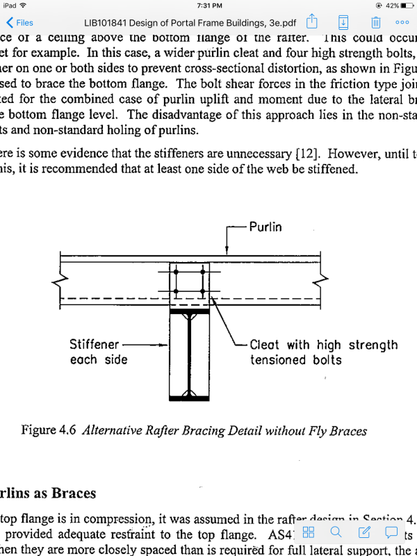
Those frames that you mentioned without fly braces, were they detailed as shown below? If so, the designers of those frames may have used torsional bracing intermittently which is a valid form of LTB bracing.

image_tdsvcj.png


I like to debate structural engineering theory -- a lot. If I challenge you on something, know that I'm doing so because I respect your opinion enough to either change it or adopt it.
 
Hi Kootk

Thanks for the great advice! I think it's a good idea to not try to reinvent the wheel for now, so I'll stick with the traditional approach then.

As for the reference on LTB restraint via stiffeners and rigid purlin connections - I haven't seen that being used in practice although it looks similar to something I have seen in the UK's SCI publications. I assume the designer makes use of the extra torsional stiffness from the stiffener + the tension flange restraint of the purlin connection.


OP said:
I assume the designer makes use of the extra torsional stiffness from the stiffener + the tension flange restraint of the purlin connection

Effectively, the web stiffeners and cleat become one continuous plate and, thereby, the purlins are able to restrain bitg the top and bottom flange at each purlin location. I've not seen it done in my market. I pulled the detail from RowingEngineers reference.

I like to debate structural engineering theory -- a lot. If I challenge you on something, know that I'm doing so because I respect your opinion enough to either change it or adopt it.
 
Status
Not open for further replies.

Part and Inventory Search

Sponsor