Continue to Site

Eng-Tips is the largest engineering community on the Internet

Intelligent Work Forums for Engineering Professionals

  • Congratulations waross on being selected by the Eng-Tips community for having the most helpful posts in the forums last week. Way to Go!

Portal framing

Status
Not open for further replies.

Hammerslinger

Structural
Nov 25, 2018
16
Recently I ran across a builder who installed a portal framed wall into an end wall with a Gable roof. The wall would only fit if he cut the two LVL beams to match the angle of the roof.

The building inspector was questioning if there was adequate wind shear resistance die to the reduced number of area for the proper nailing pattern.

My question is could this be remedied by using a fastener load calculation to see if it would resist the required load or is there predetermined criteria for portal wall construction. I'm a structural designer and former builder but I have been retired for a while and am not familiar with that type of framing.
 
Replies continue below

Recommended for you

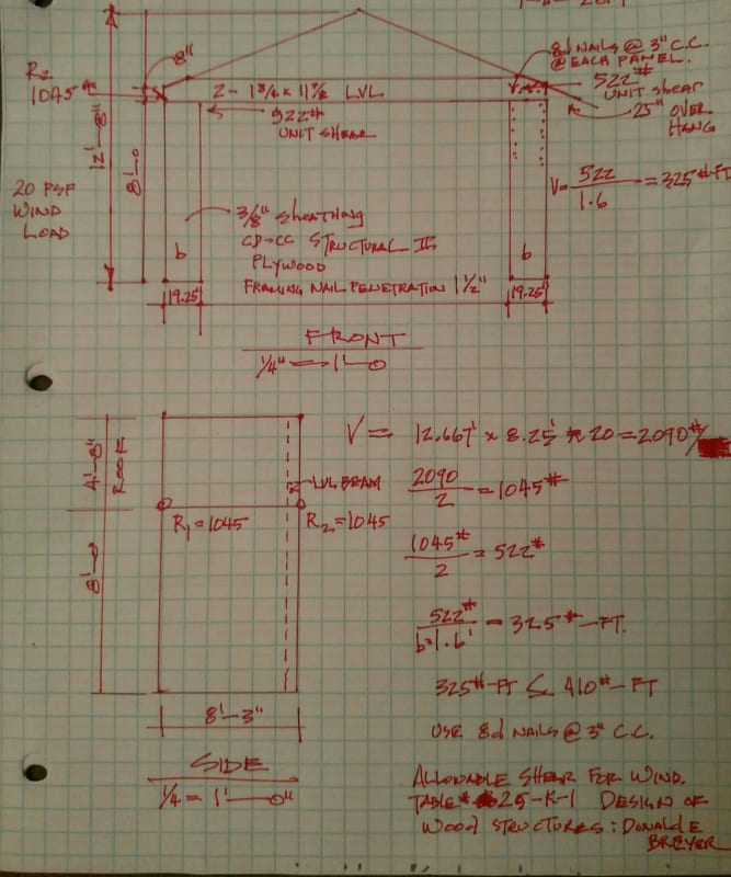
IMG_20190915_175457_d4168h.jpg
For some reason the sketch didn't attach to my post.
 
The above is my sketch of the problem. I figured wind at 20 psf. Code where I live. I didn't add the 1/3 increase for wind. Mainly I was looking for the connection of SYP to the OSB. Am I on the right path here?
 
Not sure if I understand your question, but could you brace the end wall frame back to the main portal frame ?
 
It does not appear that you are considering the moment connection (T=C force couple) that is required between your 19" wide panel and the LVL. That is the brunt of the load here. The shear is peanuts in comparison.
I have never run the numbers on a code-based portal frame as, I imagine, I would never get them to work out. I believe if I got into a situation such as yours, I would look at trying to modify the building to function as a three sided structure.
 
Then if the metal hold downs at the foundation resist the moment couple, what's the issue with the connection on the top? The framing is what keeps the panel stuff enough to resist the forces. That's my understanding of how this works. So the nailing load tables call out the number, spacing and size of fasteners. Nail it up and be done with it.

But someone always has to see some numbers even if they don't understand the mechanics behind the numbers. I think that is what the real problem is in this case. And unless you can stamp the calculations with a professional engineer seal, inspectors aren't going sign to off.

 
Hammerslinger said:
Then if the metal hold downs at the foundation resist the moment couple

They are there for the shear and some minor uplift. Otherwise it would be called "two narrow shearwalls and a beam". Most of the work is done at the beam to wall connection - hence the name "Portal Frame"
It could be designed as you speak if you could get the numbers to work out - pretty tough to do with such narrow elements. Prescriptively, it is not addressed in that manner.
 
This doc describes how these things work and might be a good place to start: Link

At the least, even with the scarf cuts you should be able to rely on at least one side of the frame for any given direction of motion.

XR250 said:
Otherwise it would be called "two narrow shearwalls and a beam".

Smart ass you is.

HELP! I'd like your help with a thread that I was forced to move to the business issues section where it will surely be seen by next to nobody that matters to me:
 
If this is a portal frame and you are using 20psf as a wind load, the bending moment should be 2090/2*8/2 (assuming equal moment to the heading and the foundation). This gives an upper bond estimate of 4200lbft at the top of the all. This gives a tension load of 4200/1.6=2525 lbs. I don't see you being able to transfer this kind of load from the plywood or wall chords to the LVL beam without some fairly complex detailing.

These are very slender plywood walls. Did you consider using prefab shear walls from Simpsons? It would be easier to take 100% of the overturning to the base and use the LVL as drag strut and connection to the shear walls.
 
You're most welcome Hammerslinger, I'm glad that you're finding the doc useful.

HELP! I'd like your help with a thread that I was forced to move to the business issues section where it will surely be seen by next to nobody that matters to me:
 
@Kootk

Looks like they are taking credit for some moment capacity at the base of the wall. Seems to be in conflict with the NC code. Have not checked the IRC yet.
The North Carolina code only requires a 670 lb shear connection per anchor at the base.
 
 https://files.engineering.com/getfile.aspx?folder=57532d2e-0005-4557-8b41-0f6434d62864&file=pf.png
Status
Not open for further replies.

Part and Inventory Search

Sponsor