Continue to Site

Eng-Tips is the largest engineering community on the Internet

Intelligent Work Forums for Engineering Professionals

  • Congratulations KootK on being selected by the Eng-Tips community for having the most helpful posts in the forums last week. Way to Go!

Position of a taper

Status
Not open for further replies.

Sem_D220

Mechanical
Jul 9, 2018
290
Hi all, it's been a while, hope you all are doing well.

thread1103-297880 is where I learned about the problematicity of applying Position to tapered features. Dean and pmarc noted that where a position tolerance is applied to a size dimension specified on the end face of a cone, as it is done in some industries, no standard provides means for a solid interpretation of whether the whole feature is required to be within the tolerance zone or just the end face (or any other local section cut where the size is directly controlled).

Can the following be a sufficient method to dismiss the ambiguity? Profile of a Surface without datum references could control the size (and form) of the cone, and a position tolerance FCF could be placed beneath the Profile FCF, similary to fig. 8-24. This way, everyone who like bonus tolerances can be satisfied (whether or not the same "bonus" for manufacturing can be achieved by other means and if it's truly beneficial here over composite profile is s topic for a completely different (old) discussion).

Everyone's input will be highly appreciated.
 
Replies continue below

Recommended for you

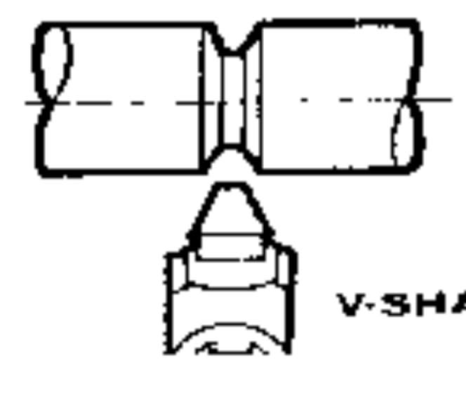
An example is a carbide insert used to perform an angled groove like in the attached picture.
20190220_060927_wq992g.jpg

The shape of the insert is akin to a flat taper, but it is actually tapered in two perpendicular cross sections (there are clearance angles).
Everything is usually defined with toleranced dimesnions, but symmetrical widths are often defined with Position tolerance. The control is sometimes required at the exact theoretical depth of cut location from the front edge.

Edit: I forgot to mention that the datum is the centerplane derived from functional features for assembly such as the 2 parallel faces of the large width shown.
 
One more point to address regarding flat tapers:
The conclusion we came to in this thread is that wedge-shaped flat tapers, similarly to conical tapers, don't have an unrelated actual mating envelope.

Following that, is it also correct to say that one cannot derive a median plane from a wedge-shaped feature? The definition of a median plane involves center points of "line segments (that) are normal (perpendicular) to the center plane of the unrelated actual mating envelope" (para. 1.3.30 of Y14.5 2009).

I am asking that because one if (edit: of the) members of this forum made an interesting suggestion recently, that flatness control can be applied on wedge-shaped feature to control flatness of the derived median plane.
 
Sem_D220,

The lack of an unrelated actual mating envelope does indeed mean that a derived median plane is undefined per ASME Y14.5-2009. If desired, the definition could be modified slightly to change this.


pylfrm
 
Thanks pylfrm.
By saying that the definition can be modified if desired - do you mean it can be done by specifying a note in the drawing telling explicitly how to derive the median plane, differently from how it is defined in the standard?

And another question regarding "centering" of flat or conical tapers. It may no longer be as relevant as it used to be before the new Y14.5 came out, but do you think symmetry (for flat) and concentricity (for conical) tapers could be a valid and viable way to center such features to a datum axis if the drawing is based on ASME Y14.5 2009? These controls are notorious among ASME users for being considered hard to inspect (is it really much harder than Profile?) but after all, these do not involve dealing with an actual mating envelope, which may be a positive aspect in certain cases such as these. What is your opinion?
 
Sem_D220,

I was actually referring to a hypothetical revision of the standard, but the drawing note is always an option as well.

Symmetry and concentricity tolerances would be valid, but I imagine it would be quite rare to find a case where they make sense functionally.


pylfrm
 
pylfrm,
Where I see this implemented is for symmetrical location of tapered features such as in the example I brought in this thread, where there is no intention to control symmetrical location with profile tolerance. Profile takes too many functions when applied and would require a completely different dimensioning method than the traditional one for this kind of products.
 
Status
Not open for further replies.

Part and Inventory Search

Sponsor