L_Fultz,
Is your plan to have this drawing fully compliant to a drawing standard, say for example Y14.5-2009 or 2018? If so - see the end of my post for some of my recommendations on other features on the drawing.*
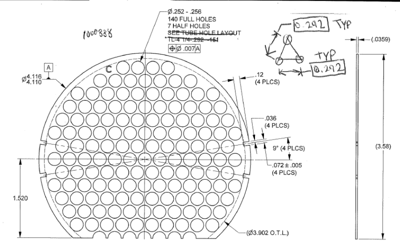
I think if I add another 0.292 basic or the 60° basic to the pattern, and change the vertical and horizontal lines through the part to actual centerlines, the holes are then dimensionally specified.
Presumably you are talking about the detail view sketched in the top right hand corner of your drawing? This could be included, with either basic or reference dimensions to give some idea of what the pattern looks like in your 2D drawing, however this could also be utilized in conjunction with 3D/math data to fully define your basic dimensions of the pattern with a note. If not, you need to somehow show the repeated relationship between instances of the pattern with basic dimensions, as well as within each instance of the pattern (ie: with the detail view you show). "TYP" notation I think can be removed and instead replaced with a number of instances.
Alternatively, I see a crossed out reference to a "TUBE HOLE LAYOUT". Is this a hole table showing (x,y) coordinates of the holes? This could be unwieldy for a pattern of 147 holes but if it is something that already exists it could certainly be utilized.
Otherwise, the central hole could be established as Datum B and the remaining hole positions could be relative to A | B.
If A in this scenario is still the OD, I would not recommend this. This would be redundant (two coaxial holes**) and not supply any additional constraint. Could you describe how this part is assembled/functions in reference to its features? If none of the shown features able to constrain the additional rotational DOF desired makes sense to establish as a datum feature then all features shown could be held only to |A| and to each other through simultaneous requirements.
I may impose a material condition on the feature, but it will not be on the datum(s).
When referenced in a FCF, all features/datum features have a material condition - RFS/RMB by default.
*Recommendations:
If so, I would recommend standardization of several of the callouts for example - nX notation instead of "PLCS". I am unsure what O.T.L. stands for, perhaps this is a well known abbreviation in your industry but it may not be to everyone - also not sure how it relates to your part, it seems to not quite lie at the full depth of the 4X slots. I'm not sure how others feel about this, but I would personally either change the notation for the 140 full/7 half holes to either fully grouped into a 147X (DIA) pattern or separate into a 140X (DIA) and 7X (DIA) patterns, removing any reference to "full" or "half".
I would also recommend utilization of position with your 4X slots - this requires a basic 9deg dimension. Profile could also be used - requiring fully basic definition.
If the interrupted bottom flat feature is at all critical, a coplanar profile could be implemented similar to Y14.5-2009 Fig 8-15. Otherwise a directly toleranced dimension could be utilized from the OD to the flat (instead of the centerline to the flat - theoretical points/planes/lines should not be references for directly toleranced dimensions) in conjunction with an orientation refinement if desired.
**There are times when this is acceptable/desired (take the case with two coaxial diameters on either end of a long part, especially to control runout). This is not one of those times.
![[pipe]](/data/assets/smilies/pipe.gif "[pipe] [pipe]")