Continue to Site

Eng-Tips is the largest engineering community on the Internet

Intelligent Work Forums for Engineering Professionals

  • Congratulations KootK on being selected by the Eng-Tips community for having the most helpful posts in the forums last week. Way to Go!

position sensing hydraulic steering. 1

Status
Not open for further replies.

oldpokey

Agricultural
Mar 27, 2007
5
Hi. New member here.

I have a question about position sensing hydraulics in a steering setup. This is a low budget project. I'd like to use a joystick to turn an articulated machine with 2 cylinders. Its an open center system.

My question is, is something of this nature possible without mounting the valving on the articulating joint itself where it has to move with the steering?

Thanks.
 
Replies continue below

Recommended for you

Oldpokey...

In basic terms, to move the two cylinders, the control valves can be mounted anywhere.

The pipework can connect from the valve to the cylinders.

The mitigating feature here is the position sensing.

What do you mean by position sensing?

Modern steering systems have priority flow control and dymanic load sensing systems, but why would you want position sensing?

It is simple hydraulics, that when you move the joystick, the cylinders will move the articulated joint and the vehicle will change direction.

This will work just fine...as long as the oil is clean and warm and the vehicle is on a flat level surface and the steering is the only hydraulic system demanding oil from the pump.

There are many questions that spring to mind, can you give some more details of the system.

Systems that have joysticks and position sensing are usually electro-hydraulic systems...those types of systems are not usually associated with the term low budget.

What else can you tell us about the system?

Regards

Adrian
 
Thanks hydromech. Yes, I'll give as many details as I can.

Ok, perhaps "position sensing" is the wrong term. I apologize if it is. What I'd like to accomplish is to have the joystick act in a very simular action as a steering wheel. By that I mean, let's say that travelling straight foward has the stick at 90degrees straight up. To turn right, I'd like to move the stick a certain amount and have the cylinders move an amount appropriate to the amount the stick was moved. Then stop turning and hold that position untill the stick is moved once again. Once the corner is negotiated, I can move the stick back to 90 and have the cylinders move accordingly. Much the same as a steering wheel would do.

By mounting the valve on the steering piece that moves different from the main frame, and operated the valve by remote cable or rod linkage, this can be accomplished. However, it would require considerable extra space and engineering. Also the plumbing would have to be considered as it would move with the valve and possibly strain the fittings too much. Especially if an obstruction such as a rock or piece of wood were to enter the mechanism.

The steering cylinders are double acting. They are sized right lengthwise for the job, so they do stroke their full length each direction. The machine I'm building is such that it will stand alone and be steered by means of "differentisl?" steering, and then when attatched to the secondary pieces, will be steered via articulation.

I can use a standard wheel and pump, but because I need the joystick to control speed anyway, I figured if I can integrate the articulating steering into the stick it would be just that much better as far as space and ease of building is concerned.

I hope that helps a little. I'm not an engineer, so I dont have the proper knowledge needed for expressing a question properly. If we are allowed to post links here, this should turn out a link to my project. It is posted on another board from time to time as I make a small amount of progress on it. If the link shows, it may help explain my situation a bit better.


Thanks.
 
What you're asking for is a position control servo.

In modern cars, there's a mechanical servovalve built into the steering box that actuates a cylinder to make the system follow the position of the steering wheel shaft (which is normally connected to the steering mechanism only by a spring). In older cars, the steering box was fully manual, and connected to a stud on a power cylinder that actually did the steering. The stud was part of a mechanical servovalve inside the cylinder, and again the input was connected to the output only by a spring during normal powered actuation.

To do something similar with an electrical joystick, you need an electrical position transducer measuring the articulation angle, and an electrical servovalve running the steering cylinders in such a way as to drive the transducer to output the same voltage as the joystick. All the pieces are commercially available ... and not real cheap.

OR, for less money, you could connect the joystick to an electrohydraulic proportional valve, which would move the cylinders as long as the joystick was not centered, but would not automatically center the articulation when the stick was returned to center.

People drive vehicles that work this way all the time. E.g. the roll axis of airplanes, where you crank over the stick to put the plane in a roll, crank the stick back to neutral when the plane has reached the desired roll angle, wait while the plane turns, then reverse the process to take the plane out of the turn. It doesn't steer quite like a car, but people can learn to do it.

I recall seeing big articulated payloaders in a salt mine a long time ago. They were steered with two electrical pushbuttons. Short push to turn a little, long push to turn a lot, push the other button to straighten out or turn the other way. The steering mechanism could have been a simple directional valve with hydraulic cylinders, or a motor with a worm gear. It didn't steer like a car, but ordinary people were driving them ... and damn fast, too. I think they were actually all electrical, with no hydraulics, so as to not contaminate the salt with oil.


Mike Halloran
Pembroke Pines, FL, USA
 
Your basic problem is that you have to create some analogue (electrical, mechanical, or just possibly hydraulic) of both your demanded and achieved joint/ram position, get them both to the same place, subtract one from the other, and use the difference to actuate the valve.

To see various approaches to this, try google searches around terms like "floating lever steering", telemotor, "Electrohydraulic steering" and "follow up steering"

Although never cheap, electronic sensing and control is probably one of the easier approaches to ruggedise.

Don't forget that as soon as you create a system with closed loop position control, you inherit a whole range of exciting failure modes. In particular, there are lots of new ways the system can fail hard-over.

A.


Thanks for taking the time to make the replies. I'm still hoping to get this done without going out of my comprehension abilities too far.

Mike, I could learn to drive it easily enough with a standard joystick directional control valve, but if I were to have to put someone completely new in it, they may have a bit longer learning curve than I can afford.:)

 
What is the expected ground speed when steering this way? I agree with Zeusfaber, you need to consider all of the failure modes to keep everyone safe. Maybe consider a sufficiently sized articulation lock when in wheels only mode.

One idea that comes to mind (but I have never seen) would be a voltage comparator/amplifier circuit. Many analog joysticks are set up so you are at 1/2 of your maximum resistance when in neutral, that way you know which way the lever is moved depending if the resistance goes up or down. You would also put a potentiometer on the articulation axis. Set the comparator circuit for zero output when both the joystick and steering axis are in neutral. Send the amplified signals out to proportional valves. The potential exists for drift due to resistance changes, potentiometer wear, etc.

You could also go digital with encoders and a micro controller which controls two amplifiers for the left & right proportional valves. About the same amount of work but fewer problems. And you could do some neat things like non-linear control to give more sensitivity around neutral but still get full steering. (I haven't messed with these controllers, YET, but "stamp" and/or "pic" controllers might be a way to go? :) )

ISZ
 
The super low budget way to do it is dispense with the discrete hydraulic cylinders and install a car's steering box with its output shaft colinear with the articulation axis. Fit a regular Pitman arm to that, and link it to the other half of the vehicle with a push/pull rod, or make up a double Pitman arm and use two rods. Then you could connect the steering box's input shaft to a steering wheel mounted in an arbitrary position with a flex cable.

The steering box's internal servo is protected from physical damage, _and_ has a mechanical backup built in.


Mike Halloran
Pembroke Pines, FL, USA
 
The machines approximate maximum ground speed will be about 12mph. It is on rubber tracks. There are several pictures of it in the link I posted. The controls will be in a small toyota pickup cab. Because of the nature of the extra long trackframes on such a narrow track guage, there will be considerably more resistance to turn. Once pointed in a direction, the machine will want to maintain that direction very well even given certain terrain obsticles.

One other bit of info that may be needed here, is that the "power pod" (unit with engine and controls) will also have the ability to push the "work pod" (unit carrying the tools). So the articulating steering control will need to have hook ups at the front and rear of the power pod.

Mike mentioned a "position control servo" and IceStationZebra mentioned the digital encoders etc. How large scale are these parts? Would any of these combinations be a simular concept to a radio controlled car or plane? That concept is perfect for this application, but need to be large and powerful enough to work the size of the hydraulic valves needed, and do so for an extended period of time.

By low budget, I guess I mean not spending 10s of thousands on it. It will take me a while to get the feel of the atmosphere here on this board. I'm used to agricultural boards. On ag boards, we use baling wire and duct tape for just about everything.:)
 
Do you need joystick control? If a steering wheel will work, the normal Eaton/CharLynn/Mico type of rotary steering valve driving the cylinders would give you more automotive type feel.

kcj
 
Hi kjc. Well, no, I really dont "need" joystick steering. And I do allready have the char-lynn valve and pump. But since I'll be having a joystick anyway for the other steering, and the speed control, I figured I could save a lot of space and maybe simplify the plumbing if I were to incorperate the articulated steering to the joystick and eliminate the steering wheel. I may end up using the char-lynn anyway, but I figured I'd try and ask about the other possibilities first.
Thanks.
 
Oldpokey - I didn't see your link the first time. I went and looked at all of the pics. A cool project - and don't worry about not having an advanced degree, school doesn't make you smarter!

A couple of questions.
1. Are you going to power the tracks on the back half? (I assume you are.) How are you going to disengage the pumps when you take it off?
2. It looks like your pumps are variable displacement with manual control of the swash plate. How are you going to control these with a single joystick? There is the Gehl skid-steer T-bar set-up, which gives you speed, direction and steering with one handle.

I also think that you could use a variation of your original idea of using mechanical linkage. I will sketch something up and post - it will be too hard to describe in writing.

ISZ
 
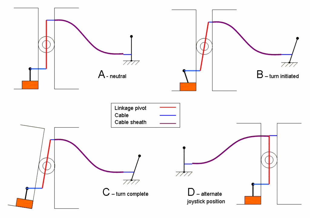
Ok, I got my drawing done. I think its self explanitory, but if not I'll answer best I can. The linkage pivot arm pivots in the same axis as your machine. The important part is that the tiller connects one half of the frame to the pivot arm and the valve is connected to the other side of the frame. If you could mount the valve on the back half you could possibly use all solid links (pic A). I'll leave it for you to determine the ratios and forces involved. I would suggest keeping the stroke on the longer side - that way the slop in the joints is a smaller percentage of your total stroke.

The concern I would have for this type of set-up is that all spool valves have some deadband around neutral. You will have to move the lever some to get the steering to move. A closed center valve will generally be more consistent than an open center valve.

On a side note I just moved from the Troutdale/Gresham OR area this past fall. I sure will miss those BIG blackberries and salmon! I promised the wife that we will move back again some day.

ISZ

steeringlayout.gif
 
Status
Not open for further replies.

Part and Inventory Search

Sponsor