Continue to Site

Eng-Tips is the largest engineering community on the Internet

Intelligent Work Forums for Engineering Professionals

  • Congratulations KootK on being selected by the Eng-Tips community for having the most helpful posts in the forums last week. Way to Go!

Position vs Runout

Status
Not open for further replies.

pmbov

Mechanical
Apr 5, 2011
28
Hi all,
I need some help clarifying position vs runout.

We have a drawing that has a hole in a round part. We call out |RUNOUT|0.010|A| where A is the outside centerline.

I want to convert runout to position (position is directional and runout is not), so therefore; it will look like: |position|Ø0.020|A|.

Now the rub, I believe this is the same thing.

When performing a tolerance stack, all of the runout value is used (i.e. 0.010 in this case), because it is the total indicator and the "zone" can move the full value.
Where position is only 1/2 the value (0.010 in this case).
i.e. radial distance from perfect.

Am I wrong, I need some kind of "documented proof" to provide to my co-worked, or something set me right and correct my error.

Help anyone?
-Paul
 
Replies continue below

Recommended for you

Your positional tolerance will allow double hole movement with perfect form. If the hole and the OD are both perfectly round and the hole center is offset 0.01 from the OD center the TIR will be 0.02. The gauge will read +0.01 in one direction and -0.01 180 degrees around.

Also, the position call out will not control form.

----------------------------------------

The Help for this program was created in Windows Help format, which depends on a feature that isn't included in this version of Windows.
 
@dgallup: "double hole movement", what do you mean by that?

The OD is datum A which is always perfect. The ID is where the control frame is. Sorry I did not make that clear. my bad.
 
Runout it's a surface control. Position it's an axis control (controls the axis on OF the unrelated axis ACTUAL mating envelope) (too much speed, I have to pay attention to details)

Runout will control position. Position will NOT control runout.


Look for October 2003: Comparison of Coaxial Controls
 
As already mentioned, the two are not the same because circular runout controls location and form, while position controls location. So I'm not sure why you want to change the symbol.
Also, your comment about the tolerance stack isn't correct -- if you really wanted to use position, the tolerance number would remain Ø0.01.

John-Paul Belanger
Certified Sr. GD&T Professional
Geometric Learning Systems
 
@Belanger:

Maybe this is where I am wrong? I was always told that when doing a tolerance stack analysis that a positional call out is always 1/2 the zone, and runout is the full zone to be used.

If I leave the position to be the same then the tolerance stack will only be 0.005?. A tolerance zone of Ø0.010 and the centerline and move only in the 1/2 the distance from perfect? Are you sating the zone can move?

I'm not saying that anyone is wrong, or I am right, I just can't seem to find a good explanation of the difference and a good example explaining the proper stack.

Also, our CMM operator would rather position over runout, also the size of the feature is very tight so the circularity is good.

Thank you in advance for everyone's help.
 
Draw a circle with a radial offset corresponding to half the position tolerance; then figure out the runout that results from that.
 
@DDave:
I did that. Can't the zone be all in one direction? I'm defiantly no measuring expert, put the gage on the surface, set to zero and rotate. Can't the gage go from 0 to 0.010 and still be to print?

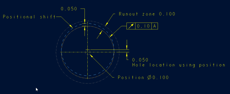
My example attached is using 0.100 for ease of viewing.

Pos-vs-runout_qq4tre.png
 
Yup - the hole moved 0.050 and the runout was double that amount, all other factors being perfect.
 
pmbov,

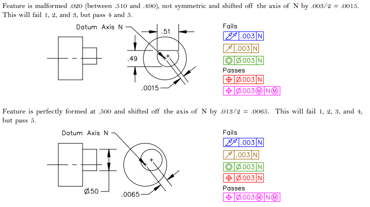
Your runout zone is not shown properly. The entire surface must fall within the runout zone (two cylinders spaced 0.1 apart) - the way you have it shown the feature (shifted blue dotted circle) violates that. A cylindrical feature of perfect form shifted off its axis by the full amount allowed by the position tolerance (position tolerance = 0.1) will result in an identical amount of total runout variation (runout = 0.1). Obviously things get much different when form variation is taken into account as the article greenimi posted (8 Apr 20 15:09) shows.

POS_VS_RUNOUT_rjpzb7.png
 
chez - it is a possible runout zone, just not one that corresponds to the offset shown by this particular feature. :)

Not sure how I missed that the runout zone limits weren't tangent, but I'll go with blurry image sampling for an excuse on this one.
 
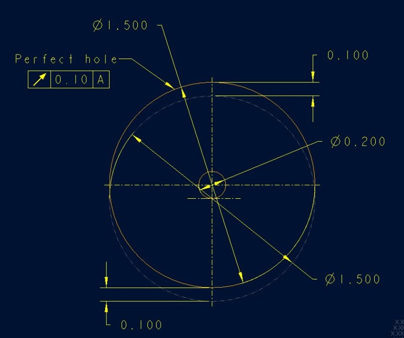
Hum? so if a |runout|0.10|A| means a zone the is 0.10 wide but 0.050 each side? So, its 1/2 the distance?
I thought it was total indication? So if you start at 0 and run the indicator and then goes to 0.10 and then back to 0. Does the centerline shift as shown?

position-vs-runout-2_jj3bak.jpg
 
A dial indicator at the 12 o'clock position will be down -0.100 and then drop to 0 at 3 o'clock then to +0.100 at 6 o'clock and then back up to 0 at 9 o'clock before returning to 0.100, for a total travel of 0.200.
 
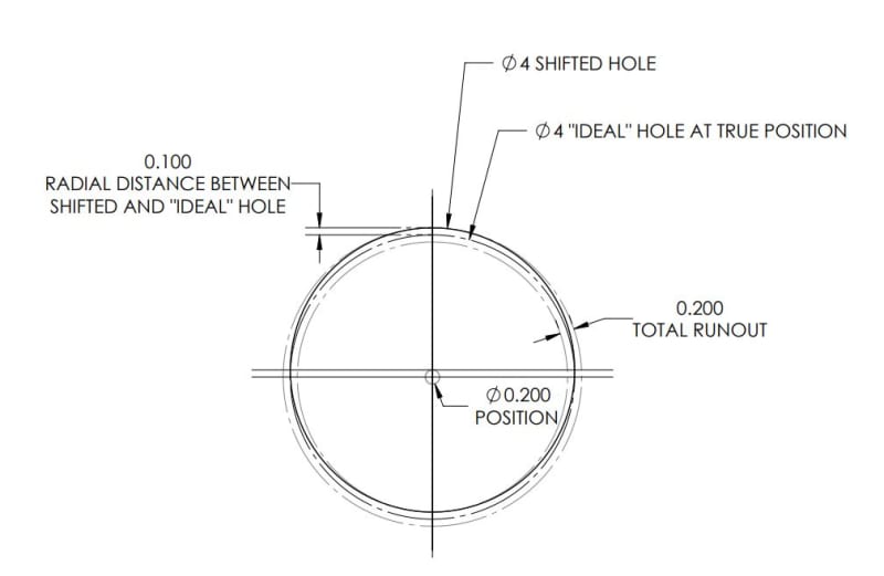
pmbov,

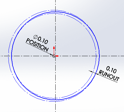
The deviation you have shown actually results in 0.2 runout, not 0.1 so it would be nonconforming. The radial distance you have labeled at the top and bottom of your figure to the "ideal" or perfect hole is the same as half the position deviation (again - for a feature of perfect form).

Apologies for the lack of color - solidworks does not have an easy way to change the color.

runout3_oeox5i.jpg
 
ok in conclusion, |runout|0.10|A| = |position|Ø0.10|A| and are treated equally in a tolerance stack. Correct?
 
|runout|0.10|A| = |position|Ø0.10|A|
For conformance purposes, no. See the article that greenimi posted earlier. (
runout_vs_position_article_utkaxg.png


and are treated equally in a tolerance stack.

I don't want to say yes or no definitively, and it depends on what is being evaluated (max axis deviation, min/max wall thickness, clearance, etc..) and assumptions made - perhaps someone else can chime in. Total runout can allow form variation which would have a UAME with an axis outside of that allowed by the position tolerance. And the position tolerance can allow form variation in the surface which would not be allowed by total runout. If we're talking about circular runout (which is the symbol you have shown in your examples) that complicates the matter even further. Whether these max/min cases evaluated for the purposes of a worst case stack would be significantly different - I'm not entirely sure.
 
ok hum, so position for location yes, but I thought it is also tilt of the centerline.
i.e. the cylinder of diameter .003 (shown above) which is the length of the feature, the centerline can tilt within the .003 cylinder, anywhere.
So it controls location and "tilt" or perpendicularity?
btw: great link
 
Yes, position controls both location and orientation within the specified tolerance.
 
Status
Not open for further replies.

Part and Inventory Search

Sponsor