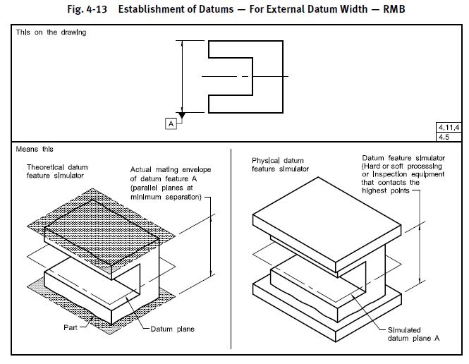
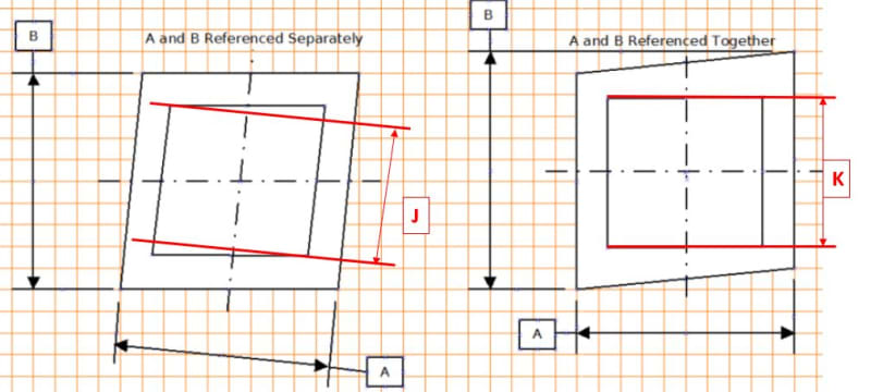
I have been reading and searching through the forum on this topic, but I was unable to find a topic which answers my confusion. I would be glad if anyone can share their opinion or facts based on the questions below. Otherwise, if there are already existing threads discussing this topic, perhaps someone can point me in the right direction.
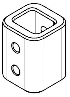
I am trying to dimension this part. The design intent of this part is that the square hole has to be centered on the part.
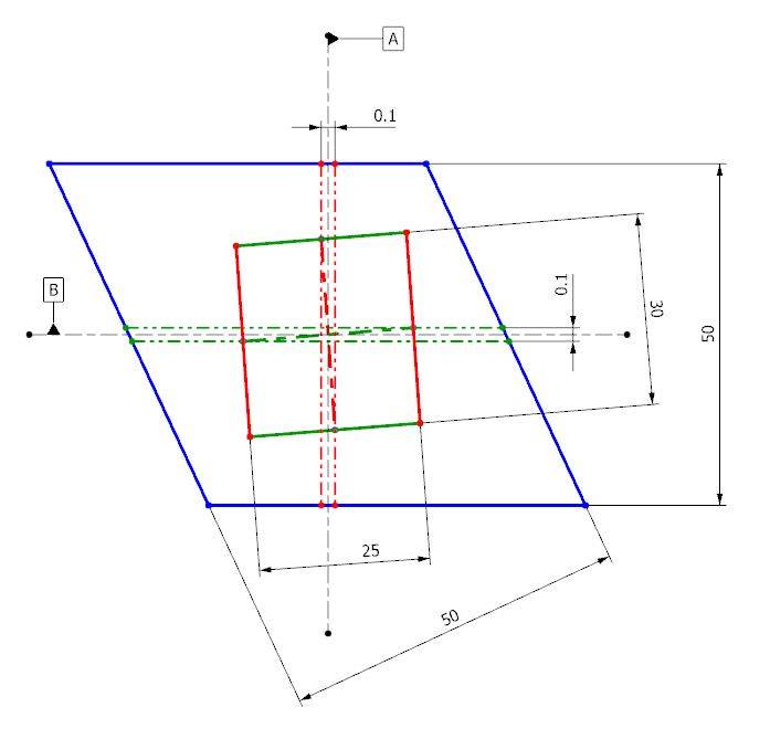
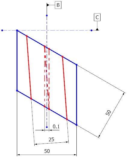
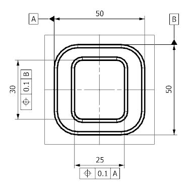
In order to control the position of the square hole, I was contemplating between the following two methods, with datum C on frontal face. Initially I went with the convention on the left thinking that since datum A, B and C are already, by default, perpendicular to each other, perpendicularity of the internal walls for dimension 30 is already achieved even with just one datum referenced. After some further thought on this, I was a little unconvinced and I had decided to call out all three datums within the control frames, as shown in the picture on the left, in order to ensure perpendicularity to the other two datums. Unfortunately, after even more time pondering upon this, I was unable to convince myself that there is a difference in meaning between the two conventions that I have posted.
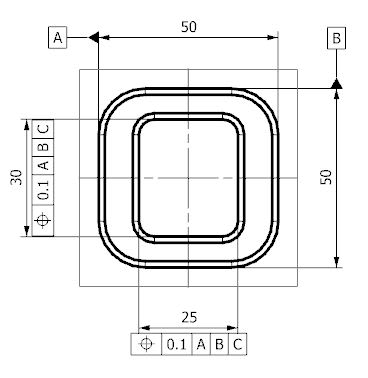
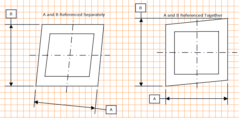
When referring to ASME Y14-5:2009, I think the closest example to my situation is Fig 7-4 and Fig 7-64 to 66. Fig 7-4 was the reason that I had decided to call out all three datums within the drawing. However, Fig 7-64 and 65 called out only two datums while Fig 7-66 called out only one datum. This was the point of my confusion.
I am trying to dimension this part. The design intent of this part is that the square hole has to be centered on the part.

In order to control the position of the square hole, I was contemplating between the following two methods, with datum C on frontal face. Initially I went with the convention on the left thinking that since datum A, B and C are already, by default, perpendicular to each other, perpendicularity of the internal walls for dimension 30 is already achieved even with just one datum referenced. After some further thought on this, I was a little unconvinced and I had decided to call out all three datums within the control frames, as shown in the picture on the left, in order to ensure perpendicularity to the other two datums. Unfortunately, after even more time pondering upon this, I was unable to convince myself that there is a difference in meaning between the two conventions that I have posted.


When referring to ASME Y14-5:2009, I think the closest example to my situation is Fig 7-4 and Fig 7-64 to 66. Fig 7-4 was the reason that I had decided to call out all three datums within the drawing. However, Fig 7-64 and 65 called out only two datums while Fig 7-66 called out only one datum. This was the point of my confusion.

