Continue to Site

Eng-Tips is the largest engineering community on the Internet

Intelligent Work Forums for Engineering Professionals

  • Congratulations waross on being selected by the Eng-Tips community for having the most helpful posts in the forums last week. Way to Go!

Positional Tolerance Usage for Symmetrical Features

Status
Not open for further replies.

Rayleigh

New member
Dec 20, 2022
12
I have been reading and searching through the forum on this topic, but I was unable to find a topic which answers my confusion. I would be glad if anyone can share their opinion or facts based on the questions below. Otherwise, if there are already existing threads discussing this topic, perhaps someone can point me in the right direction.

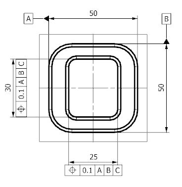
I am trying to dimension this part. The design intent of this part is that the square hole has to be centered on the part.
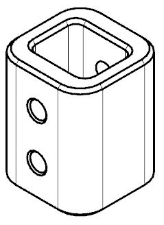
ISO_q4pxfu.jpg


In order to control the position of the square hole, I was contemplating between the following two methods, with datum C on frontal face. Initially I went with the convention on the left thinking that since datum A, B and C are already, by default, perpendicular to each other, perpendicularity of the internal walls for dimension 30 is already achieved even with just one datum referenced. After some further thought on this, I was a little unconvinced and I had decided to call out all three datums within the control frames, as shown in the picture on the left, in order to ensure perpendicularity to the other two datums. Unfortunately, after even more time pondering upon this, I was unable to convince myself that there is a difference in meaning between the two conventions that I have posted.
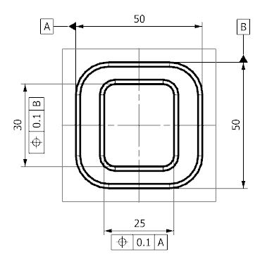
Symmetry1_luna3v.jpg
Symmetry2_hsmaf5.jpg


When referring to ASME Y14-5:2009, I think the closest example to my situation is Fig 7-4 and Fig 7-64 to 66. Fig 7-4 was the reason that I had decided to call out all three datums within the drawing. However, Fig 7-64 and 65 called out only two datums while Fig 7-66 called out only one datum. This was the point of my confusion.
 
Replies continue below

Recommended for you

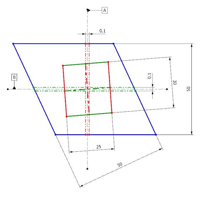
Distort the surfaces used as datum features so they are no longer perfectly perpendicular to each other.

Then look at what the two specifications mean.
 
I've included a sketch of the distortion which I assume is similar to what you mean.
Distort_odj5yu.jpg


Here is my understanding. Do correct me if I am mistaken.

Since Datum A, B and C are defined to be perpendicular in the drawing, it remains perfectly perpendicular no matter the outcome of the manufactured part. If I were to use the labeling convention in the first picture, the tolerance zone is defined with respect to Datum A and B respectively and are technically perpendicular to each other. This, I believe is as shown in the picture above. In this case, the perpendicularity between DIM 30 and 25 is limited by the size of the tolerance zone. If desired, I could add a separate perpendicularity control frame to the "vertical" edge w.r.t. Datum A to limit the extreme distortion between the two outer surface. However, as of this moment, I do not see the necessity to add the additional two datums to the positional control frames like in the second picture, as I think that it does not contribute to additional control to the inner walls of the square hole.

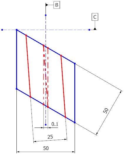
Viewed from the top, where Datum A is on the viewing plane, I believe that the outcome will be as shown below even when using the convention like in the first picture. In this case, if I am concern about the perpendicularity of the hole to the "horizontal" edge, I could add a perpendicularity control frame w.r.t. Datum A and B to limit the distortion. However, in this case, the tolerance zone for DIM 25 is still perpendicular to datum C. I still do not see how adding two more datums to the positional tolerance control frame for dimension 25 will provide additional control.
Distort2_cvvhdg.jpg


Or are the Datums also supposed to distort according to the distortion on the parts? I don't think so. Perhaps I am missing something here.
 
Rayleigh,

A few loose thoughts:

- Datum feature C reference as tertiary in the 2nd scenario adds no value to both position callouts.

- The first sketch showing distorted datum features A and B and the two position tolerance zones does not correspond to any of the two scenarios given in the first post:
--- If it was per the 1st scenario, the vertical position tolerance zone would be rotated to align with the center plane of the actual/distorted width A; the horizontal position tolerance zone would stay as is.
--- If it was per the 2nd scenario, the vertical position tolerance zone would be rotated to align with the center plane of the actual/distorted width A; the horizontal position tolerance zone would be perpendicular to the vertical one and centered about a center plane constructed from a smallest envelope contracted about the extremities of the actual/distorted width B.

- As of now, none of the two scenarios contain an orientation tolerance between datum features A and B, therefore the distortion you shown between these features on your subsequent sketch is theoretically unlimited.
 
The relations between datums is controlled by the Feature Control Frames.Datum B is not required to be perpendicular to Datum C if only Datum B is referenced and vice versa.

You need to look only at the constraints the datum feature references apply one at a time per each feature control frame.

datum_a_b_tsjzog.png
 
Rayleigh,

If you want to control the square hole including the rounded corners, you may want to consider profile tolerancing instead of position tolerancing. Figure 8-20 in Y14.5-2009 shows an example with a round-cornered cutout:

Fig_8-20_i7cwnj.png


This example uses composite profile tolerancing to control the location of the cutout loosely, and refines the form, size, and orientation more tightly. It also has the B and C datum features as single planar surfaces - you can always use the width datum features discussed earlier in the thread.

Evan Janeshewski

Axymetrix Quality Engineering Inc.
 
Pmarc and 3DDave, thanks for your pointers and sketches. I see now that I have understood the derivation of datums incorrectly.

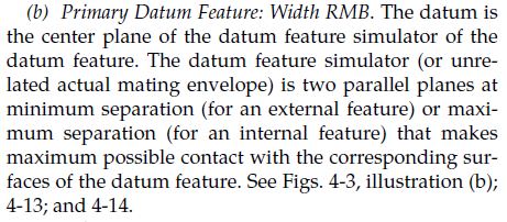
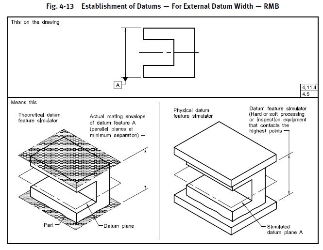
Referring to the following content within ASME Y14.5:2009 has also helped in clarifying that the Datum features affects the Datums orientation, in a way.
RMB_rcgsvu.jpg
4-13_xg134v.jpg


axym, at the moment, I am inexperienced with profile tolerancing and because of that, I have some reservation in using something that I am unfamiliar with it. Hopefully after reading up more on it more after this, I will be able to implement it confidently within the drawings.

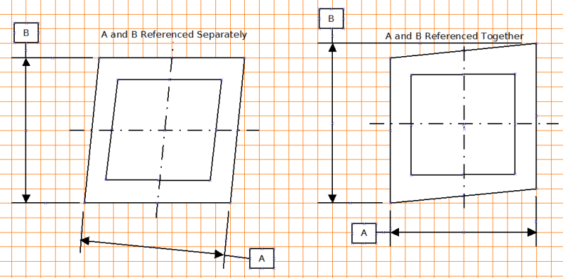
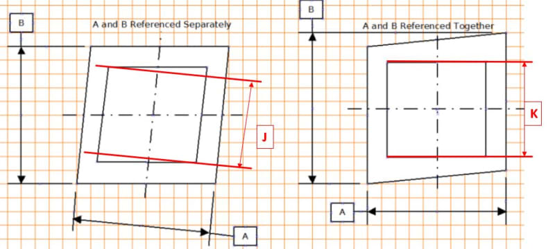
Going back to 3DDave's sketches, if I were to add a perpendicularity tolerancing on Datum feature B with respect to Datum A, am I correct that the outcome for both sketches will be almost similar? One main difference that I can think of is that if the width perpendicular to Datum A is critical, value K will always controlled better than value J.
Delta_zxwwed.jpg
 
Status
Not open for further replies.

Part and Inventory Search

Sponsor