Continue to Site

Eng-Tips is the largest engineering community on the Internet

Intelligent Work Forums for Engineering Professionals

  • Congratulations cowski on being selected by the Eng-Tips community for having the most helpful posts in the forums last week. Way to Go!

Post Buckling Deflected Shape

Status
Not open for further replies.

RFreund

Structural
Aug 14, 2010
1,885
Is there an approximate way to find the deflection or deflected shape of the a member which has buckled elastically? Or is this something that requires full on Non-linear FEA. Seams like if it has buckled elastically there should be some sort approximation, may be if the load is within a few percent of buckling perhaps?

Thanks!

EIT
 
Replies continue below

Recommended for you

If it buckles elastically, it buckles in the shape of a sin wave if the member is a prismatic section. For any section, the buckled shape can be approximated using procedures such as Newmark's Numerical Procedures.

BA
 
The theoretically accurate solution:

1) You know the 1/2 wavelength for the sine curve = column length - imposed axial displacement. So you can get lambda in the sine wave equation.

2) You set up an equation for the arc length of a half sine wave and set it to the original length of the column.

3) You use the relation established in #2 to back calculate "A", the amplitude of the sine wave.

4) Now that you have lambda and "A", the shape of your sine curve is defined and your done.

Trouble is, there's no anti-derivative for the arc length of a sine wave. As such, you're forced to result to numerical methods like the one that BA mentioned.

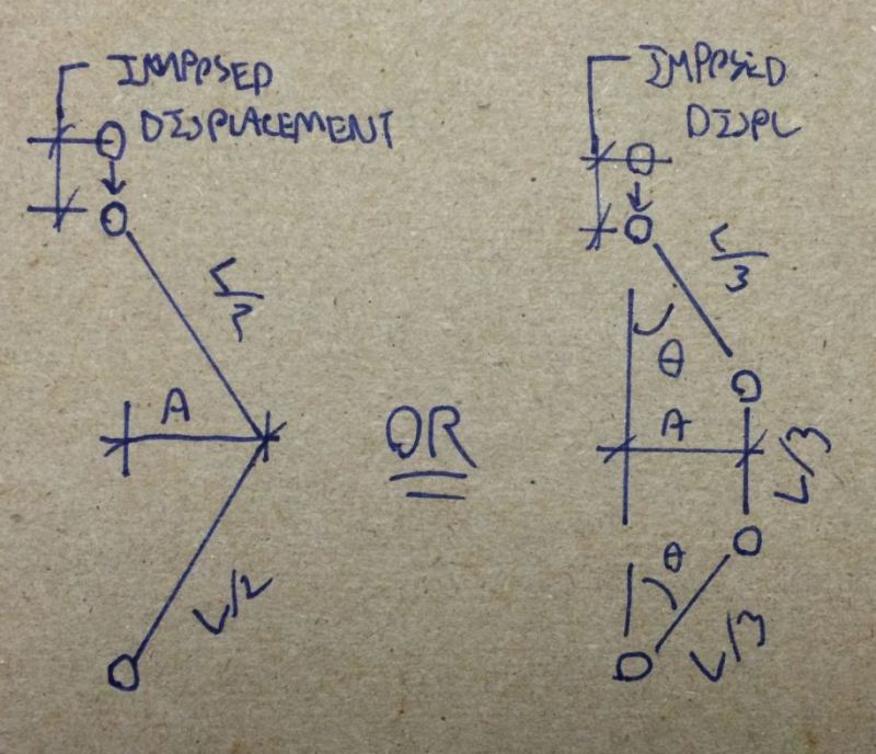
Luckily, there's a much easier way that's sure to be sufficiently accurate for any practical situation. Use the imposed displacement and one of the models below to work out "A" in the sine wave equation. This replaces steps 2 & 3 above and get's you straight to a complete equation for estimating lateral displacement along the column.

Capture2_fy7shv.jpg


Capture_zvjuhj.jpg


I like to debate structural engineering theory -- a lot. If I challenge you on something, know that I'm doing so because I respect your opinion enough to either change it or adopt it.
 
@BA -> you know I was confident that I downloaded the Newmark info when you posted it a few years ago, but I've searched and searched and cannot find it. Do you happen to still have this and is it possible to share it?

Unless it is the following document: Numerical Procedure for Computing Deflection , Moment and buckling loads by N. M. Newmark which I did find via google.

Thanks again!

EIT
 
@RFreund,
Yes, I have noticed that the Newmark procedures which I posted were subsequently omitted. There are quite a few pages, so I will have to scan them again. Can't do it right now but will try to do it in the next couple of days.

BA
 
I looked at my file and found that there are 25 pages on the Newmark Method. I also found an article by N. M. Newmark describing the method in much more detail than my earlier post. In particular, this article covers the case of axial loads on columns of variable EI. Rather than re-scan the original pages, perhaps the following article would be as good or better:


Also, Article 2.15 of "Theory of Elastic Stability" by Timoshenko and Gere covers the case of elastic buckling of a stepped column using the numerical procedure devised by N. M. Newmark.


BA
 
The following equation, for a pinned-ended column, may be useful. It comes from "Design of Steel Structures" (third edition) by Gaylord, Gaylord, and Stallmeyer. The equation is accurate within 1 percent up to delta/L = 0.25.

P/PE = 1+(pi2/8)*(delta2/L2)
 
Kootk - quick question:

Using your method -> is it possible to iterate the amplitude A until the arc length of the half sine wave matches the original length of the column. Or is the problem that you can't determine the arc length of a half sine wave (I should probably know this).

EIT
 
The problem is indeed that you can't determine the arc length. You can apporoximate it however. The sketches that I posted would make for an upper and lower bound bracket solution I think.

Given the information supplied so far, I'd run with this:

1) Use Hokie's equation to estimate A.
2) Plug A into the sine curve equation.
3) Use one of my suggested approximations to fact check Hoki's equation.

I like to debate structural engineering theory -- a lot. If I challenge you on something, know that I'm doing so because I respect your opinion enough to either change it or adopt it.
 
On second thought, I'm not sure that I know how to apply the Gaylord equation in the post buckling range (I don't have the book). Post buckling, I'd think P/Pe = 1 indefinitely.

I guess my recommendation is still the mopethod that I proposed initially, using the sketches to approximate "A".

I like to debate structural engineering theory -- a lot. If I challenge you on something, know that I'm doing so because I respect your opinion enough to either change it or adopt it.
 
OK. I may have been crutching. I used some math software and some googling. Attached is what I came up with, let me know what you think.

Buckled shape: LINK
Interestingly you get a lot of lateral deflection for not much vertical deflection.

Thanks again for the input!

P.S. Math software is free and is found at SMath Studio, great stuff if you ask me.

EIT
 
RF said:
I used some math software and some googling. Attached is what I came up with, let me know what you think.

Looks tight to me. That's exactly the procedure that I had in mind but with software doing the numerical stuff.

RF said:
Interestingly you get a lot of lateral deflection for not much vertical deflection.

I'm not surprised at all. That's just what we discussed here: Link

KootK said:
The point of the example is that, if we're discussing a case of imposed axial stud displacement resulting in weak axis buckling, it would take a great deal of weak axis lateral displacement (4"-5") to accommodate a rather small imposed axial displacement (1/2" over 8' in the example).

That software does look pretty sweet. Does it have any advantages over MathCAD express? Can you program?

I like to debate structural engineering theory -- a lot. If I challenge you on something, know that I'm doing so because I respect your opinion enough to either change it or adopt it.
 
KootK said:
That software does look pretty sweet. Does it have any advantages over MathCAD express? Can you program?
Yes, well depending on how you define programming, but yes in most senses. You can do for loops, while loops, if else, a bunch of stuff really. You can even create your own "plugins" if you have some basic coding/programming skills. It has a small but growing base of engineer users and there are some smart people (even some who used to work for MTC) who (similar to here) like to contribute. I am trying to switch all of our calcs over to it. There are some bugs for sure, but nothing that has totally deterred me. It takes some practice but once you get going it's pretty useful.

EIT
 
Baby. This could be the answer for me. MathCAD full version has been dead to me a while now and I've been lamenting some aspects of that.

I like to debate structural engineering theory -- a lot. If I challenge you on something, know that I'm doing so because I respect your opinion enough to either change it or adopt it.
 
You insert a P/PE ratio (1.001, for example) into the Gaylord equation and solve for δ. The result should be accurate so long as δ/L does not exceed 0.25 and the column is slender enough to remain elastic for the associated δ. For example, for L = 10'-0" and P/PE = 1.001, δ = 3.42 inches (δ/L = 0.0285).
 
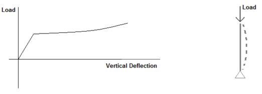
Right, but I've been interpreting this as essentially an imposed displacement situation. What value does P/Pe take on when you've taken the column to, say, buckling plus 3" of additional imposed deflection? My understanding is that load doesn't increase much beyond Pe in a slender column with further imposed axial displacement. Lateral displacement, however, clearly would.

Capture_MMM_oyv6jw.jpg


I like to debate structural engineering theory -- a lot. If I challenge you on something, know that I'm doing so because I respect your opinion enough to either change it or adopt it.
 
@Hookie93, I used this approach at first and then started thinking about what KootK just mentioned and that's why I switched methods.

Another interesting find - I wanted to find a transverse load (point load applied at midspan in the weak axis) that would cause a deflection equal to that due to a load just above the buckling load. It turned out to be about 0.05*Pe

EIT
 
Status
Not open for further replies.

Part and Inventory Search

Sponsor