Continue to Site

Eng-Tips is the largest engineering community on the Internet

Intelligent Work Forums for Engineering Professionals

  • Congratulations waross on being selected by the Eng-Tips community for having the most helpful posts in the forums last week. Way to Go!

Post installed Holdown A.B. next to cold joint

Status
Not open for further replies.

shacked

Structural
Aug 6, 2007
169
For residential construction where the seismic or wind uplift loads at the end of shear walls are relatively low I have a detail that I use when the edge distance governs the uplift.
Basically anything above 2.0kips ASD I specify this detail.

See pdf. Basically I add concrete to the side of the existing footing and dowels in order to transfer the uplift force in to the new concrete.

A plan checker is telling me that I can't do this because there is a cold joint too close to the edge and that ACI 318-14 section 17(anchorage to concrete) would treat this as a cold joint and it is un-acceptable.

I do not see an issue with this detail since the calculation already assumes cracked concrete! Is there something that I am missing? How would I persuade him to agree with me?

THanks
 
 https://files.engineering.com/getfile.aspx?folder=30dd83ce-47e2-40c8-b1c5-5e562c754d34&file=EXT_HD_DTL.pdf
Replies continue below

Recommended for you

I too don't see an issue as long as forces are developed.
How is this any different than dowelling a new foundation extension to an existing house.

P
 
If you have to post install HD anchors, it is hard to find anything that is acceptable. You are stuck with the 1.75" edge distance. There will be load transferred through the top #4 bar. I also believe that Simpsons did testing on a 1.75" edge distance that you can use. My understanding is that is how Simpson got into the anchor bolt business. Hilti wasn't interested in testing for a 1.75" edge distance and Simpson needed a product that would work. You can also argue that the Simpson product (or Hilti product) is stronger than the cast in place concrete-to-bar bond. Really, if you embed the anchor far enough, you can argue that you can conservatively use the embed and splice equations for rebar.

You should ask back to the plan checker if there was anything that they would have found acceptable. If Simpsons couldn't find an acceptable alternative on what is a real world problem, I doubt the plan checker would have a reasonable answer.
 
Are your horizontal rebar continuous through the cold joint?

Mike McCann, PE, SE (WA, HI)


"... to transfer the uplift force in to the new concrete"

So what's your proposed load path? Out of the 5/8" dowels into the existing footing, from the existing footing to the dowels, from the dowels to the new footing, and ultimately resisted by the new footing?
I`m not sure that I`m seeing that and I don't think that you can get the load from the 5/8 dowels into the existing footing.

Are you intending for the new concrete to somehow reinforce the epoxy so that you can get the load transfer that you need into the existing footing?
I`m not really sure that I`m seeing that either, unless you make some sort of Shear Friction argument...
 
Once, the new concrete added & doweled to the face of the existing footing is essentially increasing the edge distance for the new all-thread epoxied into the existing footing because the uplift force is too great with 1-3/4" edge distance for a 2x4 stud wall. Keep in mind these calculations are based on anchorage to concrete aci318-14 ch 17 for seismic loading and cracked concrete is assumed in the calculation. This is an uplift load of short duration and not a sustained load.

I guess what you quoted me as saying is probably incorrect and that is my fault for not taking the time to thoroughly describe what I believe to be occurring when the seismic load is applied. A more accurate description of the behavior would be that the dowels are creating a positive attachment of the new concrete mass to the existing footing therefore limiting the concrete breakout in the calculation since that is the governing failure more in this case. Alternately 2-#4 dowels are more than capable of resisting 3-4kips ASD load as well as resisting the tension induced between the new and existing concrete when the all-thread tries to pull out.

With that being said this detail has not been tested and I am OK using it in this manner based on my judgement. I do not just look at a calculation I also take into consideration the duration of the load and the condition of the existing footing. If the existing footing is old and not in good condition I will not use this detail. I think that this is a case where engineering judgment comes into play.
 
I honestly fail to see how this actually improves the resistance to edge breakout. In order to mobilize the steel, there will need to be an unacceptable amount of movement of a chunk of concrete first.

Depending on the magnitude of the forces, could you not face mount something to the outside edge of the foundation that is connected to your stud pack?. That way edge breakout disappears as an issue.

What magnitude of uplift are we talking about here?
 
Jayrod, you said, "In order to mobilize the steel, there will need to be an unacceptable amount of movement of a chunk of concrete first."

Based on the calculation 1.75" of side cover is not enough to develop the uplift force, from 2.0kips to 6kips. That is why I am adding the concrete centered on the HD A.B. in order to increase the side cover and the dowels anchor this concrete to the face of the existing footing.

Also, what is a stud pack? I have never heard that term before.

Thanks

 
So does this mean that if you have a crack in monolithic concrete you can not use the cracked concrete capacity? What is the difference between cracked concrete and a roughened cold joint that is held together with rebar. I think the detail does have some merit. Like I said earlier, Simpson does have pull out values for 1.75" edge distance but I can also see the logic/rationale of the detail. The rod above the new blob of concrete is just effectively a rod. The rod below the top of the new blob of concrete is just embedded into a cracked piece of concrete that is held together with rebar. You should be able to use the anchor pull out values for cracked concrete.

You should also be able to use the concrete code rebar embeddment values as well (with or without the new blob of concrete).

You can bolt on the outside of the foundation wall but this presents other issues. It can be a difficult piece of steel to protect from corrosion or potentially condensation that can rot the wood.

FYI Shacked, a "stud pack" is a built-up stud. So something like two or three 2x4 wall studs nailed together. Simpson usually requires at least 2-2x4 for a stud pack at hold downs. "Stud pack" could be a local terminology but it is fairly common where I come from.
 
To me, cracked concrete still has some significant aggregate interlock.

I've got to think about this a bit more, all I know is when I look at a cold joint like that, it does not give me the same feeling as a cracked footing.
 
Earth, I think stud pack may be local terminology, I've worked in California for 13 years and have never hears that term before.

Also, I use Simpsons anchor designer software for post installed anchor bolts and although I do get an uplift value with 1.75" edge distance it is not enough for an ASD uplift of greater than 2.1kips.

 
For better or worse, I have shown the bolt running at a slight angle to help with the edge distance issue. Only a few times and when the loads are low.
Not sure if they had to drill out the bottom of the HDU in the field. Probably ended up getting installed straight :)
 
To the folks that think the new concrete helps, what's your load path?
What does your failed shape look like? I have a hard time envisioning it.
Anybody want to provide a sketch?

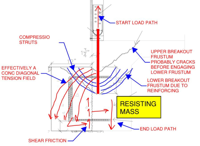
I think the best argument that I can envision in support of your standpoint is that the failure plane would still develop along the same plane as though the new concrete wasn't there, but then the top horizontal dowel crossing the failure plane prevents the failed piece of concrete from moving, thereby increasing the capacity. This is the shear friction argument i alluded to in my initial post.
To say it slightly differently, the tension in the vertical bar is transferred to the concrete, and then the horizontal dowel resists the force in shear.
In this description, the blob of concrete to the left doesn't contribute in any way.
My concern with the argument is that top horizontal dowel will only have a couple inches of bite into the failed concrete, and how much could it actually help? That, and all the traditional complaints about shear friction voodoo.


Once20036 has pretty well described my concerns. Especially with the whole rebar must be developed on either side of the joint, in this case failure plane.
 
op said:
A plan checker is telling me that I can't do this because there is a cold joint too close to the edge and that ACI 318-14 section 17(anchorage to concrete) would treat this as a cold joint and it is un-acceptable.

1) I am ignorant of this ACI provision. Can you direct me to it?

2) I'll admit that when I first saw the detail, my initial gut reaction harbored a little "ick". That said, it's my brain's job to accurately mold my gut's intuition over time. I can see why the detail has drawn some reviewer concern though.

3) On a purely technical basis, I fail to find fault with this. I envision the load path as shown below and, for me, the only real question is that which the OP has raised. Namely, does the cold joint sour things for the expanded breakout frustum?

4) I think that an important question for us to ask ourselves here, en route to any real understanding, is this: why is it okay for us to ever anchor into cracked concrete? After all, as many have pointed out, we routinely anchor into cracked concrete. I don't know the answer to this question with certainty but my feel for it is as follows:

a) The level of cracking that we're talking about is on the order of 0.3 mm.

b) I think that Mr. Poisson is our friend here and that the natural compression field that develops helps to close the joint so long as that compression is counterbalanced by some tension resistance someplace.

c) a + b = you probably still have well functioning shear friction operating on the vertical cold joint that allows the diagonal tension stresses to continue to govern the performance of the joint.

5) I struggle to see how the argument formulated in #4 wouldn't apply to a cold joint like the one that we're discussing here unless shrinkage results in a joint much larger than 0.3 mm, which I doubt. Moreover, there are all manner of cold joints routinely used in beams and slabs that are required to do more or less the same thing: stitch the transverse plane together robustly that diagonal tension continues to govern shear capacity. So there's nothing new under the sun here in that regard.

6) As shown below, I suspect that you'd develop the upper crack pattern prior to fully engaging the lower unless the upper portion is debonded somehow. I don't see this as a deal breaker, however, since we're concerned with a ULS load event here.

7) If it were me, I'd like to see the bars spaced more tightly such that you had more right behind the anchor. Maybe three rows vertically and 6"-8" OC horizontally. This is just gut feel / instinct though... no numbers.

On balance, I think that this is a pretty clever detail. I may steal it and make it my own should the need arise.

c01_dn9nki.jpg


HELP! I'd like your help with a thread that I was forced to move to the business issues section where it will surely be seen by next to nobody that matters to me:
 
In your failure mode sketch, wouldn't you need to ensure you have enough anchorage below the new reinforcing to not pull the bar straight out? I.E. bond failure, otherwise you'll never develop the lower breakout frustum.
 
I have a couple issues with the detail. We do not know the configuration of the footing but say the footing is 8" wide, your bond strength at 12.5" maximum embed is ~2600# and breakout is ~2900#. Your extension increases the strength of the connection by 700#. Your connection will be governed by adhesive strength with the configuration you have shown. To get the 6kips you mention you would have to assume the maximum embed of 12.5" and the 12" concrete the full depth but your detail will not achieve that result. To have the failure as shown in Kootk sketch the shear friction reinforcing would need to develop full capacity into your existing footing. Which you will not achieve with 6" embed. I would say if the construction joint has full shear friction you could consider the concrete monolithic. But this is not the intent of the code when talking about cracked concrete. An easier and cheaper connection would be to add two holds and anchor bolts, increasing the strength by over 900#. Which will have less materiel, epoxy, pull testing, etc.
 
jayrod said:
In your failure success mode sketch, wouldn't you need to ensure you have enough anchorage below the new reinforcing to not pull the bar straight out?

1) Sure, you need to check both breakout and bond with the lower value governing the capacity. That's just the "design" part of the exercise, though, and I'm happy to leave that in OP's capable hands. The connection has whatever capacity it has and my contribution thus far has only been meant to express my opinion that I do believe that this a legitimate connection typology with a legitimate load path and a quantifiable capacity.

2) I would take the development / anchorage length of the rods to be 8", measured from the top of the new concrete. What leads you to believe that this should be measured from the elevation of the new dowels?

sandman21 said:
But this is not the intent of the code when talking about cracked concrete.

What informs your opinion on that? I'd love to see a silver bullet document saying "breakout frustums shall not cross construction joints". I've done a fair bit of looking and not found such a thing however. If you could point me in the right direction, I'd be grateful. I've dabbled in high-rise facade connection design and, in that space, you see anchors and embeds straddling construction joints left, right, and center (parapets, up-stand beams, etc). If those designs need to treat construction joints as free edges, we may need to set up a travelling road show to educate folks on that.
 
 
sandman21 said:
The key is making them into a construction joint. You need to provide sufficient anchorage of the concrete to allow the anchorage concrete failure cone to develop.

Alright, so that's just math/design then, right? You're not actaully opposed to the concept of taking a breakout frustum across a properly reinforced construction joint?
 
Status
Not open for further replies.

Part and Inventory Search

Sponsor