Continue to Site

Eng-Tips is the largest engineering community on the Internet

Intelligent Work Forums for Engineering Professionals

  • Congratulations SSS148 on being selected by the Eng-Tips community for having the most helpful posts in the forums last week. Way to Go!

Post-tension 7 wire strand bending stress

Status
Not open for further replies.

Baffled Engineer

Structural
Jul 27, 2018
60
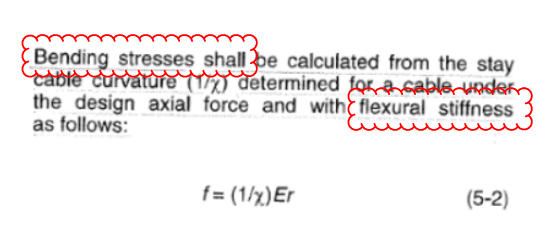
I am designing a new post-tension system for an existing timber truss. A requirement from the stay cable design guide (PTI DC45.1) is I include local bending stresses from the turning points of the post-tension wire in addition to the axial stress.

When I calculate the bending stress per the equation provided (see below), I am getting 6200 mPa of stress which is way above the specified tensile strength of the new 7 wire strand I plan on using (fs'= 1860 mPa).

I find the radius of curvature of the turn is too tight but the existing post-tension system on the timber trusses have a tighter radius of curvature which clearly works. I was wondering if anyone can provide me comments on how this works and how I can make it work with the same turning point. Thank you.

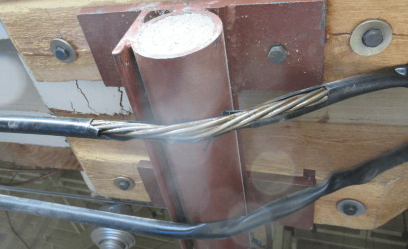
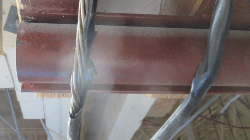
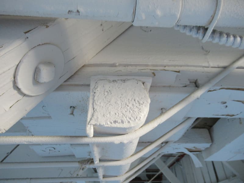
This is a picture of the existing turning point.

IMG_2045_nvqs4z.jpg


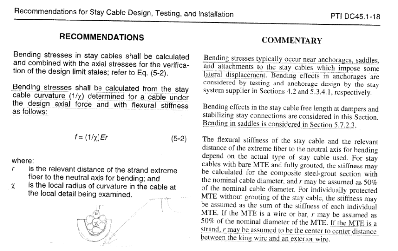
This is the formula from PTI.

Formula_eng0qj.png


radius of curvature of the turn = 130mm
7 wire strand dia. = 12.9mm
X = 130 + 12.9/2 = 136.5mm
E = 197000 mPa
r = c/c of king strand to outer strand (per PTI) = 4.3mm

f,bending = (1/x)Er = (1/136.5) * 197000 * 4.3 = 6205 mPa
 
Replies continue below

Recommended for you

I'm finding it hard to believe the strand can't just bend at that radius without any plastic deformation, so as you surmise something ain't right!

But the equation appears to be correct, easily derived from consideration of the strains (for example see here where they derive the same equation).
 
f is a flexural STIFFNESS (units of MPa) and not a bending stress (also units of MPa).
 
You have a truss bar in the photo vs. cables. Are you asking how the truss bar works? How it can sneak around a tight corner like that?
 
I’m very interested to hear the answer to this one. Your equation appears to match the guidance provided, which means the cable should snap like a twig before you even apply the axial load!?

As above, I’m finding it hard to believe that this has any meaningful effect in reality, let alone cause a problem of this magnitude.
 
I disagree with the assertion it's a flexural stiffness. Wrong units for a start. The equation is a strain times young modulus, this equals stress. (see the link I posted as it derives the equation)

Now the issue is this equation is suitable for solid sections (like a solid bar bent at a radius), and not suitable for helical wound strands as there is inherent slip between the strands that results in a low flexural stiffness compared to say a 12.9 diameter solid rod, which if you bent it to a radii of 130mm would clearly exceed the yield stress. Which is exactly what the equation is telling you.

See this paper as it discusses some of the concepts involved.
 
Yeah I know it says that, I just don't believe it. Again take a look at the link I posted and see if you agree.

I would have thought a flexural stiffness has kNm/m/rad units?
 
I think it means calculate for a cable (with bending stiffness) the stress as follows. Just seems poorly phrased?
 
Throwing it out there also that EI = bending stiffness = N/mm^2 * mm^4 = Nmm^2.

The attached pdf is quite useful as it relates the radius to a reduction in capacity. It refers to a formula in a Norwegian standard that you may be able to investigate further.

An interesting problem, to which there there doesn't seem to be a great consensus.

If the manufacturer had an equivalent moment of inertia, you can come at it from the perspective of determine the moment from the curvature. Then stress from the moment.
 
 https://files.engineering.com/getfile.aspx?folder=e5a48f28-0e74-496c-8133-1cd5cce6003d&file=Master_thesis_Bart_de_Jong_30-10-2015.pdf
Agent666 said:
Throwing it out there also that EI = bending stiffness = N/mm^2 * mm^4 = Nmm^2.

The attached pdf is quite useful as it relates the radius to a reduction in capacity. It refers to a formula in a Norwegian standard that you may be able to investigate further.

An interesting problem, to which there there doesn't seem to be a great consensus.

If the manufacturer had an equivalent moment of inertia, you can come at it from the perspective of determine the moment from the curvature. Then stress from the moment.

Thanks Agent666 I will read that document. I also agree with you. I know for a fact that the derivation of the normal stresses generated by flexural bending of a beam is the same equation as what's shown in the guide, which is the inverse of the radius of curvature multiplied by the modulus of elasticity and the distance between the extreme fibre and the neutral axis of the beam. Also, flexural stiffness or rigidity have units of Nmm^2.

Agent666 said:
I disagree with the assertion it's a flexural stiffness. Wrong units for a start. The equation is a strain times young modulus, this equals stress. (see the link I posted as it derives the equation)

Now the issue is this equation is suitable for solid sections (like a solid bar bent at a radius), and not suitable for helical wound strands as there is inherent slip between the strands that results in a low flexural stiffness compared to say a 12.9 diameter solid rod, which if you bent it to a radii of 130mm would clearly exceed the yield stress. Which is exactly what the equation is telling you.

See this paper as it discusses some of the concepts involved.

The existing trusses have an 8mm diameter post-tension wire (solid) as shown in the picture. I don't think it's any different than a beam in flexure but I could be wrong. Bending those existing wires to that curvature would have yielded the extreme fibres of those wires followed by the addition of the actual post tension stresses. I don't know if the bending stresses can be ignored similar to stirrup reinforcement where the rebar is bent 90 degrees, or if the equation is limited to small strains or curvature. I did find a recommendation in the guide suggesting a minimum radius of curvature of 2m

I agree there would be a slip in the helical strand if bent to that curvature, which I believe the guide takes into account by allowing you to use the distance between the centre of the king wire to the centre of the outer wire instead of the king wire to the extreme fibre of the outer wire.

BUGGAR said:
You have a truss bar in the photo vs. cables. Are you asking how the truss bar works? How it can sneak around a tight corner like that?

The photo shows the turning point of the existing 8mm dia. post-tension wires. I'm interested in determining and rationalizing the correct magnitude of bending stresses in the solid wires based on the tight radius of curvature and how I can incorporate, in general, bending stresses caused by the turning point into the design of the new post tension wires. I hope this clarifies my question.


Strange rule. I’d like to understand what it’s getting at.

All bent reo fails this test.

Same as dead end onions. They’re well and truly yielded.
 
Tomfh said:
Same as dead end onions.

For our North American colleagues, this is what Tomfh is referring:

CAPTURE_PT_DE_gb4xvm.jpg


Commonly used in bonded PT systems for slabs and beam incorporating single-stressed strands in a multi-strand flat duct (3/4" deep, typical with a max of 5 strands per duct).

Both the mechanically deformed ends ("onion") and a nominated bare-strand length form the bonded non-stressing end-anchorage.
 
What you might really be after in these types of things is the residual stresses, you bend it, it yields (and undergoes some strain hardening) it springs back a little when released (recovering the elastic deformation. It's a bit like curving a structural member like an I-Section. Some residual stresses are locked in from the rolling process.

To work our the residual stresses you need to recognise that it's the stress resulting from the difference between the elastic and plastic moduli.
 
Most of what I've seen on this suggests that the issue at play is fretting of the wire group and the impact that would have an the fatigue performance of something that might be sliding back and forth across the deviator thing during its load history.

For a solid, ductile thing under static, self limiting bending load, you could probably just "pull" through any bending / residual stresses. Truly turning the rod into a rope so to speak.

 
Below are pictures of a similar configuration but from a different building.

You can see the strand/s actually unravel at the turning point and the cover is ripped. I'm concerned this is due to the bending stress (and/or bearing stress?), which may or may not have been taken into account during the original design of the existing post tension system.

Turning_Point_1_z5vppz.png


Turning_Point_2_mvq3uw.png


The document Agent666 provided shows a short and simple reduction factor in the axial capacity to take into account the forced bending stresses on the strands. It seems rational and it compares well with tests results so I think I'm sticking with that formula instead of the PTI formula, which appears to be limited in application. Thanks guys.
 
To prevent/minimise the unravelling, I'd think you could feed it through a steel guide pipe of a similar diameter which is bent to the correct radii? Weld it to the anchor block thing if needed. Sort of becomes a long term durability issue if its lost the protective sheath around the bend.
 
Yes, that's what we were planning on doing. We're going to install a steel guide pipe to try and confine the wires. I sort of drew it in the second picture just below the equation from PTI. Thanks for the input Agent666 much appreciated.
 
What we can see on the above pictures is not allowed.....regadless of formulas
 
Look at how pulley grooves for wire rope are shaped. The the radius of the groove is very close to that of the rope for the reason shown in your picture. A coil spring of suitable dimensions could be slipped over your cable.
 
Status
Not open for further replies.

Part and Inventory Search

Sponsor