Baffled Engineer
Structural
- Jul 27, 2018
- 60
I am designing a new post-tension system for an existing timber truss. A requirement from the stay cable design guide (PTI DC45.1) is I include local bending stresses from the turning points of the post-tension wire in addition to the axial stress.
When I calculate the bending stress per the equation provided (see below), I am getting 6200 mPa of stress which is way above the specified tensile strength of the new 7 wire strand I plan on using (fs'= 1860 mPa).
I find the radius of curvature of the turn is too tight but the existing post-tension system on the timber trusses have a tighter radius of curvature which clearly works. I was wondering if anyone can provide me comments on how this works and how I can make it work with the same turning point. Thank you.
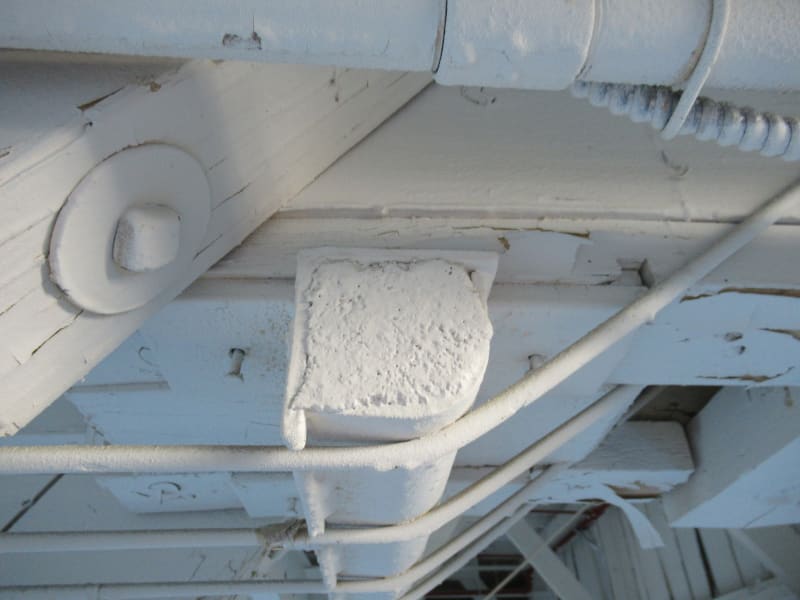
This is a picture of the existing turning point.

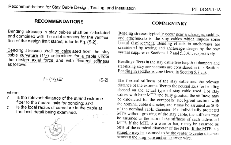
This is the formula from PTI.

radius of curvature of the turn = 130mm
7 wire strand dia. = 12.9mm
X = 130 + 12.9/2 = 136.5mm
E = 197000 mPa
r = c/c of king strand to outer strand (per PTI) = 4.3mm
f,bending = (1/x)Er = (1/136.5) * 197000 * 4.3 = 6205 mPa
When I calculate the bending stress per the equation provided (see below), I am getting 6200 mPa of stress which is way above the specified tensile strength of the new 7 wire strand I plan on using (fs'= 1860 mPa).
I find the radius of curvature of the turn is too tight but the existing post-tension system on the timber trusses have a tighter radius of curvature which clearly works. I was wondering if anyone can provide me comments on how this works and how I can make it work with the same turning point. Thank you.
This is a picture of the existing turning point.

This is the formula from PTI.

radius of curvature of the turn = 130mm
7 wire strand dia. = 12.9mm
X = 130 + 12.9/2 = 136.5mm
E = 197000 mPa
r = c/c of king strand to outer strand (per PTI) = 4.3mm
f,bending = (1/x)Er = (1/136.5) * 197000 * 4.3 = 6205 mPa
