Continue to Site

Eng-Tips is the largest engineering community on the Internet

Intelligent Work Forums for Engineering Professionals

  • Congratulations cowski on being selected by the Eng-Tips community for having the most helpful posts in the forums last week. Way to Go!

Potential for hydraulic transients with liquid restriction orifice isenthalpic expansion

engineerlad123

Mechanical
Apr 27, 2025
1
Hello,

I am evaluating running a line that connects to the discharge side of a pump where the pressure is approximately 800 psig. A block valve would be opened daily to fill from this line to an atmospheric vessel after the vessel goes through a restriction orifice. My question is that with the block valve closed the pressure on the other side of the restriction orifice before the block valve would be at the same static discharge pressure as before the orifice. Would there be a transient situation in this case where at the very beginning before steady state the block valve itself would be subject to that significant pressure drop? I'm evaluating this with a low vapor pressure liquid (MDEA) if that helps.

I guess I'm also just looking for good references/texts on this sort of design (taking a high pressure line and reducing it either for sampling or filling of a smaller system). This is more of an academic exercise unless I'm severely over-estimating the potential risk involved here as there are other options to work with that don't require pressures that high.
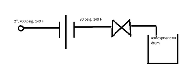
1745757209136.png
 
Replies continue below

Recommended for you

The intent of the restriction orifice (RO) is to have a controlled flow to the atm tank. Put the RO downstream of the block valve.
Yes, the block valve will see a DP of 700 psig when you open it. Once, the flow starts, there will be pressure drop across the RO that will stabilize the line pressure.
 
Last edited:
Doesn't really make much difference which side of the RO you put ot as there will be a transient in both cases as the valve opens and before steady state conditions exist.

How long this goes on is dependant on valve opening speed, impact of the flashing liquid and length of lines , but is a transient thing so could be 5 seconds, could be 50 seconds before steady state flow exists. It will also happen when you cease flow as the pressure drop will move from the RO to the valve as flow slows down and stops.

But how will your fluid respond to the RO? If it's low vapour pressure won't it flash anyway? MDEA looks fairly high vapour pressure to me.

Where does 30 psi come from? That is quite a pressure drop on a pipe with an open end to atmosphere.

You sometimes see needle valves or choke valves used which are more resistant to flashing liquids and more complex trollable when starting and stopping.
 
MDEA actually has a really low vapor pressure compared to water - 1 Pa at standard temps. I don’t have a lot of experience with higher pressure liquid systems where flashing is a concern so I can’t speak if that’s actually a high vapor pressure considering this dP.

Isn’t it the opposite where a lower vapor pressure results in less flashing?

The 30 psi was just a stand in number assuming friction losses from the RO to the atmospheric tank. Honestly I could run swage tubing with a choke valve but I wasn’t sure on the reliability of that versus an orifice plate. If the alternative solution is taking off the suction I would need a pretty reliable proposal to justify the alternative.
 
If the line is liquid-filled the transient will be gone in milliseconds when the block valve opens. The dangerous situation is if you have air (or other non-condensible gas) trapped in the line at 700 psig.
 
That RO is probably sized to prevent overloading this line with excess flow that could potentially rattle and shake this line off its supports, given line pressure is 700-800psig. So its not meant for operational throttling. Add a choke or needle valve either upstream or downstream of the current manual block valve for operational throttling.
 
Yeah that was my original intention.

@katmar Yeah I need to confirm with process if there’s any potential for MDEA+CO2 before I ponder anything else
 
I would size the orifice for two to three times the actual desired flowrate with a globe throttle valve downstream to tweak the flow to what you really need. The entire system piping would be designed for the maximum operating pressure of the upstream system. I agree with Kumar about the transient conditions of the system but don't know why that really makes a difference to you as to why you really care about transient conditions. You will still design for steady state conditions with full upstream pressure designed for all piping downstream of orifice.
 
Are enginelad123 and YungPlantEng the same guy?
Transient, isenthalpic expansion, low vapor pressure, ETC .
Probably I missed the point here!

Pierre
 
Last edited:
For such a large pressure drop, a small orifice size may be required. Hence, it will be better to have a series of orifices to reduce the pressure drop per orifice.

The small orifice size will tend to be blocked by dirt, so the valve should be placed upstream of the orifice to enable cleaning.

Also, a manual throttling valve to control the flow so that the liquid does not overflow will be helpful.

For a 2" size with a properly controlled flow, the transient effect will not be significant.
 

Part and Inventory Search

Sponsor