This is connected to at best an educational project, not a commercially viable one. This is completely outside my field. Any answers, explanations, and (online) references would be greatly appreciated.
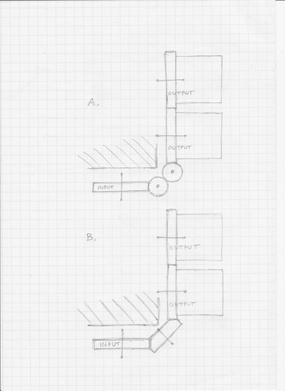
The mechanism has a gearwheel A that needs to drive gearwheel D (and E). A's axis is horizontally 90 degrees from D's axis and they are separated by some space. Can horizontal wormgear A drive a vertical worm B, that in turn drives a vertical worm C, that drives a horizontal wormgear D, that in turn drives a horizontal wormgear E?
Searching, I failed to find illustrative examples of such successions. Individual contact interfaces yes, but combinations is where I failed. I found explanations why a spur wormgear doesn't drive a worm, but I'm unsure of helical wormgears, and I'm still wrapping my head around hyphoid.
The (tentative) reason for two worms is restrictive space considerations. D and E drive parallel-axis cylindrical objects; there is some friction and some other stresses, but torque need not be transmitted further, if (and when) that is a consideration.
Thank you for your patience... I hope this turns out useful for someone beside me. I'm sure this forum has a lot of readers not directly looking for their work stuff. While there's no escape my question is a pretty daft one.