Continue to Site

Eng-Tips is the largest engineering community on the Internet

Intelligent Work Forums for Engineering Professionals

  • Congratulations KootK on being selected by the Eng-Tips community for having the most helpful posts in the forums last week. Way to Go!

POWER DROP 3

Status
Not open for further replies.

rajm008

Marine/Ocean
Oct 22, 2015
44
What is the design characteristics in a pump that decides the power drop point? During testing of pump after the 150 % flow the power keep on increasing to a point after which either the power drops or stabilizes. How to bring down the point(not below 150 % flow )?

can anyone help me out?
 
Replies continue below

Recommended for you

Look at the pump curve.

All will become apparent by looking at the head generated and the efficiency curves

For centrifugal pumps ( you don't say which one you are looking at)

As you increase in power past the duty point the efficiency is normally quite high or drops a bit, but flow increases and head stays more or less the same hence power goes up.

As you increase flow, the efficiency goes down, which means more power, but the head starts to drop off faster than the drop in efficiency which although you have more flow overall the power levels off or drops a bit.

All this is HIGHLY pump dependant, which is why pump vendors issue pump curves


Remember - More details = better answers
Also: If you get a response it's polite to respond to it.
 
What do you mean by power point drop? Your question isn't sufficient for any useful answer - although LittleInch has given you something to think about.

It is a capital mistake to theorise before one has data. Insensibly one begins to twist facts to suit theories, instead of theories to suit facts. (Sherlock Holmes - A Scandal in Bohemia.)
 
I meant power drop point as the point in the power curve of centrifugal pump where the power starts dropping. It should happen after 150 percent flow. but i want to make it happen close to 150 percent flow. Changing motor wont help as it is dependent on pump design.
 
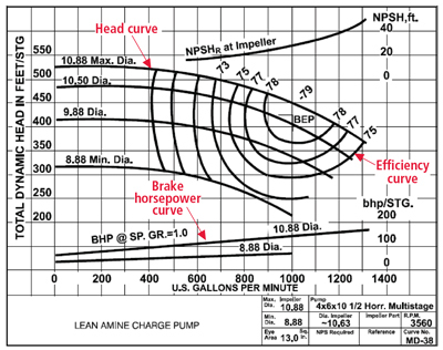
To bring down max power you need to get your duty point on the RH end of the curve, at or beyond Best Efficiency Point (BEP)

E.g. in the curve below, if your duty point on say the top curve was say 600 GPM then there is a large rise in power as flow increases.

If on the other hand you had specified 1000 or 1100GPM as your duty point on the same pump, you would only have up to 1300GPM before you went off the curve, but max power would only increase by ~20% compared to rated power. Like I said - it's all down to the individual pump curve and why you're trying to limit max power. It's all down to good pump selection. Vendors will often try and give you a pump which matches their models, but alternatives are available.

pump_curve_elecha.jpg


Remember - More details = better answers
Also: If you get a response it's polite to respond to it.
 
Thank you for the answers. As you said its all depends upon pump selection. In order to be on the safer side and pass some tests my vendor selected a bit bigger size foreseeing the requirement of power drop. Now that the model is already selected and got the approvals for materials used , I was thinking if there anyway of making the power drop happen without changing the model and making some change is design like impeller eye dia or design.I have to show the power drop happening.
 
What makes you think power will drop as flow increases?
The only time power might reduce is if NPSHr greatly exceeds NPSHa, but then the pump will be suffering cavitation and may even hunt up and down its performance curve. Neither of which is recommended.
If you need to limit power input you should consider fitting an orifice plate in the discharge.


It is a capital mistake to theorise before one has data. Insensibly one begins to twist facts to suit theories, instead of theories to suit facts. (Sherlock Holmes - A Scandal in Bohemia.)
 
"I have to show the power drop happening. "

Please explain why.

You size and choose a pump based on a duty requirement. It's all about matching pump duty and service. if you choose a bigger pump than you need "to be on the safe side", but do nothing about the system then you will flow more fluid and use more power.

Please describe your system and provide more data if you want this thread to go much further

If you flow more fluid through it than rated flow then you use more power.

If you want to limit power, limit the flow

Remember - More details = better answers
Also: If you get a response it's polite to respond to it.
 
If your intention is to prevent a fixed speed pump from going to end of curve and tripping on startup due to overload-overcurrent, as would happen with a hot standy pump going through an auto startup sequence, one common way of doing this, when you are stuck with a given pump, is to install a flow control valve on the pump discharge,and have this modulated by a high set FIC.

A soft start feature on the pump motor may or may not work in this application with this concern.
 
I agree with the assumptions made by a couple of our learned commentators above that restricting the flow will be the only solution to tripping problems. Higher flow will require higher power. Nothing is for free, no magic, except if you improve impeller efficiency. "Chasing" the power drop off zone for whatever reason does not create value and is not good engineering.
 
What power drop-off?

It is a capital mistake to theorise before one has data. Insensibly one begins to twist facts to suit theories, instead of theories to suit facts. (Sherlock Holmes - A Scandal in Bohemia.)
 
The power drop is important for a fire fightinig pump . Its an extra safety measure to ensure power wont keep on increasing to motor burns. This case is very rare tht the pump goes to that point. but in fre fighting pumps we do take that extra measure. I have attched a data table showing the power droping off.

Please see the table attched.

This pump (340 m3/hr rated flow,511m3/hr is the 150 per flow point)was tested with a motor of 185 rated KW.

You can see that after 511 m3/hr we kept on increasing the flow and we got the power drop at 576 m3/hr at 266kw . Where the power dropped from 266 kw to 261 kw.

What i am trying to achive is to bring this value some where close to 150 per flow , like say 530 m3/hr or so.
 
 http://files.engineering.com/getfile.aspx?folder=4f78c293-0517-4b16-bea6-afc2609f8652&file=power_drop.jpg
What are you talking about, the data you supplied shows an increase in power as the pump runs out on its curve, there is no "power drop-off".
You are running round in circles, time to involve someone who knows what they are doing for your particular application.

It is a capital mistake to theorise before one has data. Insensibly one begins to twist facts to suit theories, instead of theories to suit facts. (Sherlock Holmes - A Scandal in Bohemia.)
 
I don't understand how at your rated flow, you have a motor power consumed (column 6) of more than your rated motor power. This is taking design to the limit and doesn't comply with any pump specification I've ever seen, far less a fire pump.

At 266kw that 185 kW motor would be running pretty hot(!)

You need a bigger motor. I would go for 275kW.

Or a smaller pump.

End of story.

Remember - More details = better answers
Also: If you get a response it's polite to respond to it.
 
The shape of the power curve depends on the specific speed of the impeller, does it not? So, if you want to change the shape of the power curve, you'd have to change the impeller design.
 
Yep, go full axial and you will get falling power curve as flow increases. But that doesn't address the OP's confusion.

It is a capital mistake to theorise before one has data. Insensibly one begins to twist facts to suit theories, instead of theories to suit facts. (Sherlock Holmes - A Scandal in Bohemia.)
 
Actually, it does. The 'design characteristic' that determines the power drop point, as he/she put it, is the specific speed of the impeller.
 
Status
Not open for further replies.

Part and Inventory Search

Sponsor