Continue to Site

Eng-Tips is the largest engineering community on the Internet

Intelligent Work Forums for Engineering Professionals

  • Congratulations KootK on being selected by the Eng-Tips community for having the most helpful posts in the forums last week. Way to Go!

power transients 3

Status
Not open for further replies.

v6racer

Electrical
Sep 30, 2005
13
Hi, to start my degree is in micro electronics so power distribution isn't my strong suit despite working through college as a journeyman. The journeyman stuff was why I have been asked to look into this.

Anyway, on the 480 volt power to some of our crystal furnaces we have some regularly occurring transients that our process guys insist are affecting yield. These are +- 1% which is well within the spec for incoming power. I have confirmed that it is most likely incoming power as I have seen the pattern on two different substations. Supposedly we do not have automatic power factor correction or on load tap changers and can't say those would match the data. Any idea what would cause the changes shown in the pic below?

Since the process engineers insist it affect their yield I will have to mitigate these changes. I am thinking either a rotatory or battery UPS. Can you suggest anything else I might want to look into?
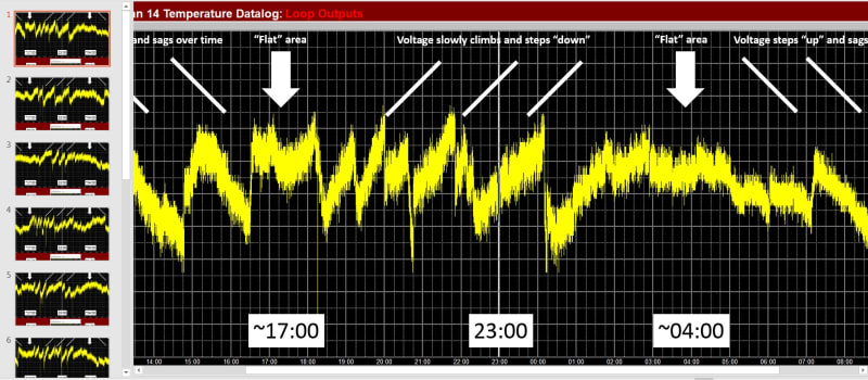
overview_s6glfa.jpg
 
Replies continue below

Recommended for you

Your facility may not have on load tap changers, but virtually all power utilities do; the graph shows what I would consider a completely normal voltage trend for a typical utility over a 24-hour period.

Not knowing what they are, I can't speak to the effect this would have on "crystal furnaces," but if there are multiples of them it might make sense to apply whichever manner of correction you may choose, such as some type of static VAR or machine terminal voltage compensation, to just one of those units, normally the reputed worst offender for example, and see if its yield improves. The results should make it clear whether the capital expenditure on the balance of the machines is warranted.

CR

"As iron sharpens iron, so one person sharpens another." [Proverbs 27:17, NIV]
 
Yep, what crshears said. That looks like perfectly normal feeder load profile. Load goes up during the day, increasing voltage drop on the system which the substation LTC responds to by increasing the voltage. Multiple times. Then at night the opposite happens, load come off, the voltage rises and the LTC lowers it. Also multiple times. Probably not anything outside your facility that can/will be done about it, you'll need some form of power conditioning in-house if it needs be dealt with. The furnace manufacturer seems unaware of the real world.
 
Thanks CR. The crystal furnaces are for growing exotic semiconductors and the temperatures need to be controlled to tight tolerances at the molten/solid interface to ensure a uniform crystal lattice orientation. It takes a few weeks to run and unlike the silicon and germanium crystals usually grown these generally don't come out uniform so the yield is very poor.
 
You're welcome, Racer, although now that you've said a little more about your process and that the controlled variable is actually temperature, I think I'll stand aside and see if there are other contributors better qualified than I to speak of temperature measurement and control loops...holding the supply voltage dead flat may not necessarily "yield" the end result you're hoping to achieve.

CR

"As iron sharpens iron, so one person sharpens another." [Proverbs 27:17, NIV]
 
That is pretty whack all right.

What's the voltage matter? Why aren't the PIDs keeping the temperature spot on? You've got a large thermal mass and voltage that's shifting over an hour and the PIDs can't cope with that? Something is wrong that's not the voltage.

holding the supply voltage dead flat may not necessarily "yield" the end result you're hoping to achieve.

Is a very good point.

How many watts are the furnaces?

Keith Cress
kcress -
 
I agree with itsmoked.
This ooks like someone is "Guessing" that someone else is responsible to fix the problem.
Add to that, try to cover the symptom without solving the problem.
That graph is interesting but not particularly useful.
I don't see a voltage scale.
On a positive note to solve the problem:
How about some graphs of the furnace temperatures?
Do these graphs correlate with the voltage fluctuations?

An anecdote of a real problem to illustrate the effect of solving the wrong problem.
I was sent out to look at a lumber drying kiln.
Lumber drying is very forgiving but there are limits.
Originally the pen was "Painting the chart".
The pen never stopped.
It went from large overshoots to large undershoots and back to large overshoots.
The actuator was constantly moving.
The heat source had a wide turn-down ratio and the output was controlled by a pneumatic actuator.
Some one had tried to smooth out the temperature by adding an adjustable restriction in the control air line to the actuator.
That limited the overshoots but left different but still unacceptable undershoots.
The second solution was a pair of check valves and a second restriction.
One rate for increased output and a faster rate for decreasing the output.
I shook my head and ripped off all of the hardware.
I installed an airline from the controller to the actuator such as had been originally used.
Then I dialed the controller from 0% proportional band to 10% proportional band.
The chart straight lined.
They had never seen such a steady temperature.
Your solution may be as simple as an adjustment to the PID controller.

We need more information.


Bill
--------------------
"Why not the best?"
Jimmy Carter
 
Furnaces are 48kva and heat to ~1200C. Voltages/power matter because the liquid/solid interface is held to within +-.01 C of the melting point or as tight as they can get it. It is hotter toward the liquid side and cooler on the solid side by a few tenths over a few feet. The 5 volt tap change causes a brief spike or sag that the PIDs catch but they are set to very slowly adjust and are over damped I think. The 30-90 minute changes of 5 volts don’t cause a problem. The idea is to start crystallization at the seed and keep a uniform lattice structure while moving the transition zone over the melt (like 6 feet per week). Cool spots, eddy currents and other things cause unwanted crystallization, localized changes in the metal ratios and a host of other issues.
 
Then there needs to be constant voltage power conditioning equipment between the utility and the furnace. There’s no utility out there that would look at that plot and see a problem to be fixed. Furnace manufacturer needs to design for the real world.
 
Maintaining +/- 0.01C at 1200C is an extreme technical challenge. This usually requires a very well insulated chamber with a temperature controlled "guard" chamber around the insulation, and then more insulation around that.
 
Thanks for the added details v6racer.

Here's a route you could look at. Probably the cheapest by far.

Get a 6 gang Variac with motor drive. Good for 480Vac 70A (you need about 57A)
6 gang cased
M6020-6YE would be the model number (motorized and enclosed)

Then get one of Variac's motor controllers that control the aforementioned motor via 0-5V or 4-20mA. You'd want the reduced range setting to control the voltage to 0.25%.

FRC-20 Controller

They'll tell you how to provide the control signal.


Keith Cress
kcress -
 
The tolerance is very tight at that range, as CompositePro stated. Even sensing temperature with that small an uncertainty is difficult. I'd like to know more about the temperature sensing method.
What type of sensors are used? What is their uncertainty? How many are used? How are they installed?
Are temperature transmitters used? If so, what is their total uncertainty?
I'm guessing that digital controllers are.used. What is their A/D bit count and associated resolution? What is their scaling?

xnuke
"Live and act within the limit of your knowledge and keep expanding it to the limit of your life." Ayn Rand, Atlas Shrugged.
Please see FAQ731-376 for tips on how to make the best use of Eng-Tips.
 
Good solution Keith, but I have to challenge this statement:
Here's a route you could look at. Probably the cheapest by far.
I would go with a set of 5 KVA-480:48 Volt transformers configured for an auto-transformer boost.
Then instead of the 60 KVA Variac, use a 5 KVA Variac to drive the primaries of the boost transformers.
Your control scheme may be used.

Bill
--------------------
"Why not the best?"
Jimmy Carter
 
Here is a chart showing the input 480 voltage and the DC heater power on different units and zones. The furnaces were custom made in house 30 years ago because they couldn't find one designed for the job. The controls have been upgraded, heater elements get changed out regularly but the basic design has remained the same. They are experimenting with several new versions now and they recently hired a whole slew of materials and chemical engineers to bring the yield up from the 20% range now that volume has grown to the point where they need much more materials monthly.

HB_power_yzkiwk.jpg
 
OK Transformer magician. Great idea! I bet it would improve the accuracy even.

Well too.. There's your correlation Bill in v6racer's latest graphs.


Keith Cress
kcress -
 
I can handle basic Proportional and some Integral, but not so much Derivative.
v6racer, You may consider posting a message in one or both of the controls fora and see if a PID expert will look in on this thread and suggest the best tuning for your application.
If there is a tuning solution that may be the best and cheapest solution.

Bill
--------------------
"Why not the best?"
Jimmy Carter
 
It is also possible to use the measured input voltage value as a feed forward input to the temperature control loop. Then if the input voltage varies the controller output would instantly change, without waiting for temperature change to occur first. This may be what the graphs are showing us is actually happening. What is the definition of "zone output"? Voltage, current, power, control signal? It would be good to see actual temperature variations on the graphs. If input voltage is changing, a controller output should be changing to compensate, in order to keep temperature constant.
 
That may work well Compositepro.
Another possible solution may be adding a Watts transducer and controlling the Watts to the heater rather than the current.


Bill
--------------------
"Why not the best?"
Jimmy Carter
 
All of the graphs have been data collected by the controller. Zone output is the SCR power output going to the heater element. There are multiple RTDs sensing temperature in 8 different major zones and 4 minor zones around the transition area. The heat up rate is limited because two of the metals produce an exothermic reaction when combined that can blow apart the furnace if allowed to go too fast. That's why I said the controls where over damped.
 
That does not seem to make sense. You want the SCR output power to stay the same regardless of the AC input voltage. If the input voltage goes down the SCR's should stay on for a higher duty cycle to keep power constant. The graphs show that the output goes up when the the voltage decreases. This would make sense if the graph represents the signal going to the SCR power controller, which is calling for the SCR to stay on longer to keep power the same. I think you are confusing the two. The signal to the SCR power controller is going up in order in order to keep the power output constant as input voltage goes down. That is a good thing.
 
Status
Not open for further replies.

Part and Inventory Search

Sponsor