yamehyameh
Civil/Environmental
Hi All,
I attempted my local Professional Engineer Exam and was stumped by this and several other questions. It's quite humbling to be honest. The exam is open-book and written. We have approximately 50 mins for each question. I'm not sure how I can complete this within the time limit using only hand calculation. There is a combination of point loads and udl on a catilever beam with an overhang. Any advice or suggestion would be appreciated. The question is as follows:
Question 1
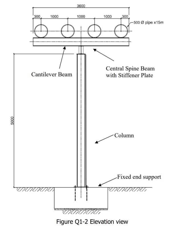
A segment of a long pipe rack system is shown in Figure Q1-1. The main
structural system comprises columns spaced at 6m centre to centre supporting
a central spine beam connected the columns. The cantilever beams that support
the four water pipes are spaced at 2m centre to centre. The 500mm diameter
water pipes have a self-weight of 2 kN/m length and when the pipe rack system
is in operation the variable action is 2 kN/m length. The arrangement of pipe
rack system with dimensions is shown in Figure Q1-2.
The section of the cantilever beams and central spine beams are both UB
305x165x40. The section of the columns is UC 203x203x60 (Class 1 section) of
5m height. The columns are rigidly connected via baseplates to concrete
footings. The bottom flange of the cantilever beams are welded to the top
flange of the central spine beam. The client expects the pipe rack system to be
designed to cater for any configurations in the use of the pipes during operation
and during maintenance periods.
All steel sections are grade 355 N/mm2. Steel section properties are provided
in Annex. Refer to figure Q1-1 for additional information.
(a) Under a critical loading case when two pipes are removed for maintenance
on one side of the pipe rack, determine and sketch the ultimate bending
moment and torsional moment diagram of the pipe rack system, including
the central spine beam, cantilever beam and column
(b) State the effective length (bucking length) to be considered for the design
of the columns and the cantilever beams with explanation.
(c) Check the adequacy of the column to SS EN 1993 using the critical load
case in Q1 (a).
(d) Suggest possible improvements with justifications to the pipe rack system
in a clear sketch.


