Continue to Site

Eng-Tips is the largest engineering community on the Internet

Intelligent Work Forums for Engineering Professionals

  • Congratulations KootK on being selected by the Eng-Tips community for having the most helpful posts in the forums last week. Way to Go!

Pre-Engineered Metal Building Roof Rod Bracing 4

Status
Not open for further replies.

Rabbit12

Structural
Jul 23, 2014
477
I've designed a few foundations for metal buildings but I don't claim to be an expert on the load path the PEMB manufacturers use. My question is specific to the rod bracing you commonly see in the roof of these structures. They installed some rod bracing that is bent pretty bad. I got a comment from a PEMB supplier's project manager that says these are non-structural elements and are only used to square the building. I had always thought these braces created a diaphragm. Am I wrong?

I'm going to challenge the statement and want something in writing from the PEMB manufacturer but wanted to check here with the experts in case they try to pull a fast one.
 
Replies continue below

Recommended for you

I think the outsized roll over door played major role in decision making to stiffen the first bay, as both the positive and negative pressures due to wind is quite critical, similar to human909 addressed in a few threads above.
 
retired,

Correct on the reason for the bracing, but not the correct door. That door has a post that comes down from the ceiling which acts as a mullion. The door is more like a curtain than a traditional door.
 
Purlins can take axial from the end wall to the first bay of roof bracing.

Wall panels are sometimes used as diaphragm as a function of wall panel, girt spacing, insulation, fasteners, and openings.

Roof panels sometimes consider diaphragm, but not often more than the width of the purlin spacing. This is a function of purlin spacing, insulation, fasteners, and framed openings.

Sometimes roof x-bracing is actually used for squaring items like canopies. I would expect it to always be tension-only.

I doubt a PEMB manufacturer would miss negative wind pressures- almost all of them have their own software and checking scripts which check for this.

If the rollover door has a post, half of the wind still goes through the roof. If bracing weren't placed in the end-bay, then it's likely that all of the purlins would be nested until encountered the braced bay. I'll admit, I don't know what's going on in the bracing porn image: I don't know which company allows their rigid frame bottom flange braces to terminate anywhere other than purlins?

The MBMA should have some guidelines on how erectors deal with unsheathed buildings and the effects of winds during erection.
 
The rod bracing usually on the roof and between column, which is the secondary structure, its uses to keep the stability of the building, the rod bracing is necessary and important.
 
Just an update on this.

I challenged the project manager to produce a stamped letter from the PEMB EOR stating the rods were non-structural and if so they could be removed (because they were bent). Miraculously, the rods got replaced with straight rods. I'm guessing the PM found out the rods were indeed important.
 
In the end, it was canwesteng who was correct. Not your problem...

Thanks for the follow up
 
SteelPE said:
Here is some metal building bracing porn for you

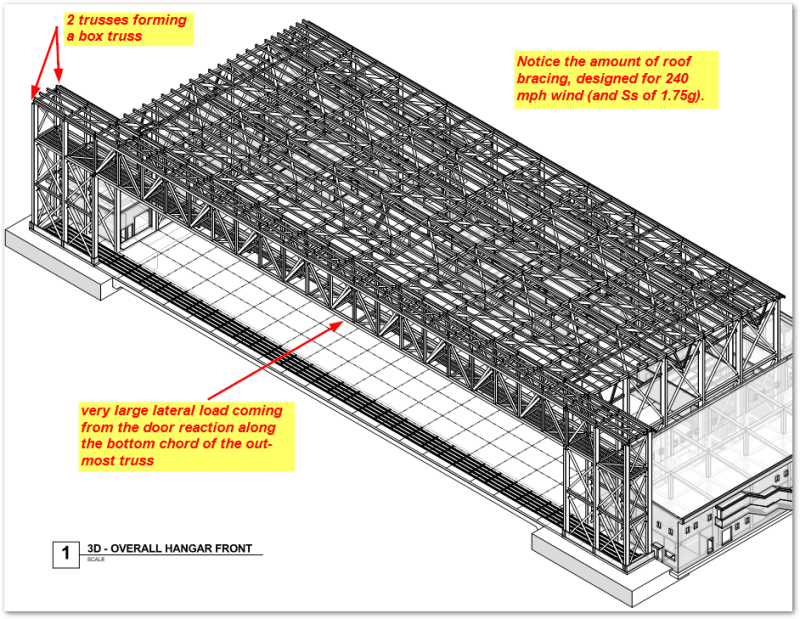
This is the door truss at a hangar with a fabric/curtain (or rigid, doesn't matter) door. Because of the large lateral load, a single bent frame (or truss) will not work. One typically ties the first two gravity elements (bents, trusses, etc.) together to create a box header truss/bent. Also, often the end bays experience the high wind uplift, putting the bottom flange in compression, with the need to brace the bottom flange accordingly. See the attached pic...

As far as the original topic, I've done 6-8 PEMB buildings (foundation design, PEMB shops review) and 100% had horizontal bracing in the roof which continued to a X-brace in the walls (90%) or a portal frame (10%). There are no diaphragms with the SSR (standing seam roofs). While any system might have some in-plane shear strength (even drywall on 2x4s will carry 50-70 plf), this is only working for some nominal wind loading. No way in PEMB hell can the roof panel withstand the "design" wind load for strength. I don't understand why PEMBs would be exempt from structural theory - the bldgs don't know they are PEMB. If there is no in-plane stiff enough diaphragm, you need a horizontal truss. The rods/cables are designed for Euler buckling (min compression to allow for the model to converge as FEA model) with the purlins transferring compression between non-braced frames. The knee braces seen in the pics above help to reduce the KL span of the purlins and/or girts. I've never seen a PEMB work in a diff matter than this.

header_truss_ecd64v.png
 
I have worked on a few Butler buildings years ago that used a roof diaphragm. They sent me tables showing the design capacity. Not sure if I can locate them, however.
 
XR250,

Back in the day (~20 to 30 years Back) Butler had tables for diaphragm bracing. Those tables only applied to screw-down metal panel, i.e. Butlerib II, and they involved the use of a lot higher number of fasteners to structurals. Butler no longer supports those tables.

Tension only rod bracing in the roof and wall planes is primarily what Butler supports these days. There are some other bracing schemes supported as well, i.e. Windposts, Portal Bracing in the wall planes and some compression/tension bracing.

I want to note, I in no way am attempting to speak in any official capacity for Butler Manufacturing Company.

Jim
 
Status
Not open for further replies.

Part and Inventory Search

Sponsor