Eng-Tips is the largest engineering community on the Internet

Intelligent Work Forums for Engineering Professionals

Pre-FEA Hand Calculation Methodology 2

Status
Not open for further replies.

Doodler3D

Mechanical
Jan 20, 2020
188
0
16
US
Hi.

I want to figure out a methodology for reliable hand calculations prior to any FEA analysis. I'm having a hard time try to limit what falls under 'hand calculations' as there always exist a complex, semi-empirical equation in a reference book or research article. I'm training, so there's a long way to go before getting actual jobs.

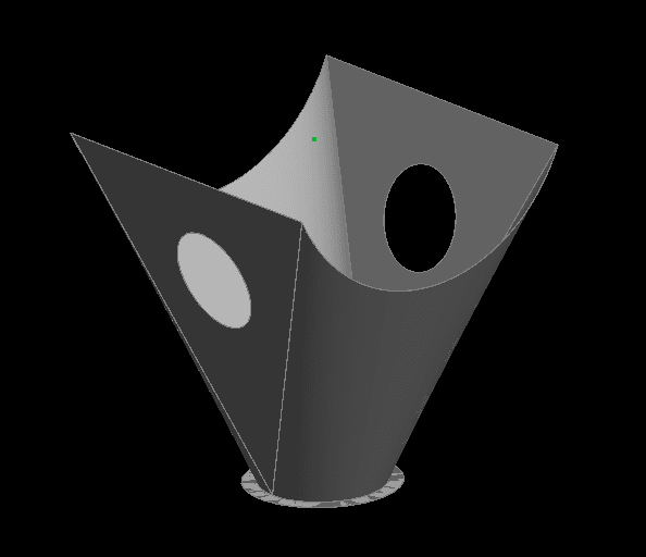
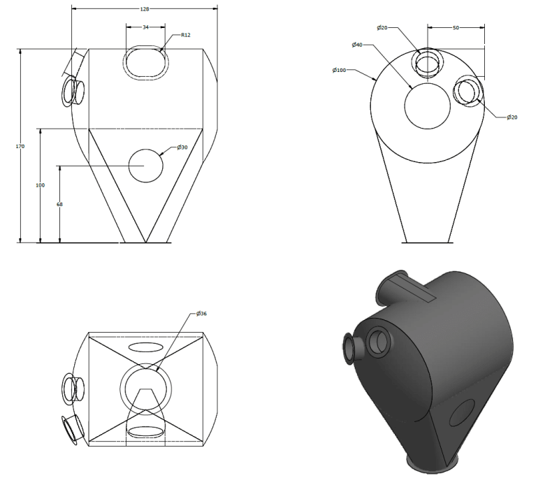
Below is a fictitious thin walled mixing vessel, fabricated from 12 gauge, SA240. The vessel must sustain 45" WC vacuum, or roughly 1.6 psi.

Here's the model:
Screenshot_252_dg55ub.png


My method would be as follows:
1. Check the shell for stress
2. Check torispherical vessel/dome head stresses from Roark's
3. Use Omer Blodgett and figure out the weld stresses at all nozzle-shell joints using thrust forces
4. Check the stresses/max deflection transition section from Timoshenko/Roark's
5. Check the bending stresses and deflection of a combination of stiffeners and flat sheets on the transition section
6. On sections of least stress, figure out the location of two lifting lugs

I'd appreciate any constructive suggestions, advise, insults, jeers, ridicule, sneers and taunts. Better safe than sorry.

Thank you.
 
Replies continue below

Recommended for you

Follow up question:

Since the vessel is under external pressure, what are the essential, simplified buckling stability checks for the model?

Thank you again.
 
Follow up question 2:

How do I know whether the formula used from codes/handbooks etc. are suitable for my analysis?

Thank you again.
 
I used to do structural analysis before FEA, or more accurately, as FEA was being adopted at my employers. When they got their sticky little fingers on it they built an FEA model of a car, compared the results with real world, and realised they had an enormous problem. Well, a lot of enormous problems. So they built a simple welded structure out of flat sheets, continuously welded along its seams, and compared that. I was back at uni when they did that, I don't know what the result was. So by the time I'd graduated they'd restricted themselves to modelling various joints in the car and comparing it with hand calcs, which is where I came in. So, I armed myself with a few textbooks, and, crucially, my manager threw Bruhn at me, and expected me to use it.

TLDR: plus roark

Cheers

Greg Locock


New here? Try reading these, they might help FAQ731-376
 
Thanks Greg. I just got a soft version of Bruhn. But how do I decide that I need hand calcs at a certain location on my structure?
 
DoodlerDaru,

You do calculations done by any method because there is something important that you do not know, but that you are able to work out somehow. Someone may have to review this afterwards?

I do calculations by hand either because the FEA cannot extract the information I want, because I don't have convenient access to FEA, or because I want a sanity check on FEA results. I run FEA because the problem is difficult to solve by hand, and because I want a sanity check on hand calculations.

When you finish your calculations, what will you do with them? Do you study them, make design decisions, and relegate the calculations to a design folder? Has someone challenged the safety of your design and demanded calculations they can review? Are you justifying a design decision to management?

Perhaps there is a hand-calculation methodology that reliably produces safe results!

--
JHG
 
JHG, thankyou.

To elaborate further and get some clarity, I'm considering just the transition from the vessel.
How would I idealize or break down a hand calculation (since its not a standard shape) for this part for external pressure and axial loading? Is there a thought process that deems certain calculations as absolutely necessary prior to FEA?

Screenshot_254_uvdg9y.png
 
DoodlerDaru,

I am not a pressure vessels guy. If this were my problem, I would probably tell management to take it to someone who analyses pressure vessels.

How do you think your vessel will fail? Those large wall areas will buckle under the pressure at some point. Axial force on that bottom flange will fail in buckling too.

--
JHG
 
JHG, it is not a pressure vessel, but a mixing vessel that will experience vacuum under certain operating conditions. I do understand that the walls will fail in buckling. Since hand calculations are complicated for this structure how do I go about validating an FEA analysis? It is the simple stuff that is confusing. For example, I could Roark's for a simply supported triangular plate, that would be erroneous, right?

 
Could you start by approximating the shape as a shell of revolution? I.e. treat it as a pressure vessel.
If so, no need for Bruhn just yet (it doesn't look like semi-monocoque which is most of the content in bruhn). Try one of your solid mechanics texts from university. The hand internal loads methods in bruhn can be just as complex and fraught as FEM.

With FE validation, break the problem down into several Fe models of increasing complexity, so that you can understand by hand calc or otherwise the incremental change between each model. The simplest model you should be able to validate against a hand calc.
 
Ng2020, Thank you.

A hand calculation from Bruhn is another method of approximation for problems that are complex. With FEA, we are trying to validate one approximation with another within 5 to 10% error? Therein lies my confusion. What happens when simple models from Burhn's/Roark's may not be the best way forward? How do you break a complex problem down to something that could be close to an exact solution?
 
Łukasz Skotny of enterfea.com has many great examples of analyzing such structures, and he's doing a series in which he analyzes certain problems first using hand calculations, then linear FEA, and finally nonlinear FEA. The first set of worked solutions is for a web under a local load:


Animacja-Z_uuwo57.gif


- Rob Campbell, PE
[link Practical Precision]practicalprecision.com[/url]: Precision and optomechanical design resources and services.
 
DoodlerDaru said:
it is not a pressure vessel

It's a closed volume, subject to a pressure differential across the wall, which you expect to fail due to said pressure differential.

That, my friend, is a pressure vessel whether it's sole purpose of existence is to contain pressure or not.

I make this point not to disagree with you for the fun of it- but to point out that if the failure you expect is due to pressure (and not due to something else like localized mechanical stress from a lift point or whatever) then the methods usually used to analyze pressure vessels will be instructive to you.

DoodlerDaru said:
What happens when simple models from Burhn's/Roark's may not be the best way forward

Short of going back to first principles and doing a great deal of high level math to develop your own model, using simplified mathematical models (whether you get them from Roark's or not) is your only real option.

Prior to the advent of computers, this is exactly what was done, and still is done when the situation warrants it. You have to accept the fact that an approximation is all you are going to get; you're never going to hand calc a model that will yield exact, precise results without a loooooong time (months, perhaps years, either way impractical) modeling, testing, adjusting the model with test results, and modeling again.

With that said, break your assembly into components. If a side of your component looks vaguely like a supported triangular plate, well, Roark's has an answer for that. Calculate, sanity check, extract information needed to simply model whatever that triangular plate touches (edge forces or moments, etc) and move on until you have a complete set of information, or until you are close enough to complete to meet your needs.

 
Well now you come to mention it - hand calcs were done by, or at least with the direct oversight by, specialist stress analysts with years of experience. FEA is frequently performed by spotty faced youths/youthettes. I once was asked (paid) to reengineer the chassis of a 1955 Thunderbird to improve its torsional stiffness. OK, I thought, with FEA I should be able to show those old guys a thing or two. Ha. Torsionally the frame was already correctly designed, the only way to make it stiffer was to improve the joints by using non production feasible methods, or up gaging all the sections. There was no weak point as such. Of course the 55 Tbird was designed by people who had recently been designing aircraft at the limit of technology, they probably thought cars were a bit easy.

Cheers

Greg Locock


New here? Try reading these, they might help FAQ731-376
 
If you have access to FEA, and you have the shell models, why not just run the FEA? Even the ASME code has limited hand calculations for external pressure (I believe an appendix in ASME Sect. 8 Div.1) and many of the components (inside pressure vessels to not technically code items) that I've designed didn't fall under the appropriate curve in the code calculations, but that was a good approximation. Running an shell/plate FEA took less than an hour to do, most of the work was building the model.
 
@CodyK, I can run an FEA analysis easily .... 2-3-4 million dofs and more. But that's 10% of the work. I'd say that 70% of the job is getting hand calcs to validate the model. Again, I can use something like Roark's, but those are all idealized, semi-empirical calculations. A real analyst will probably spend long nights doing math with Stefan Timoshenko. For me, that stage will come after many years.
 
'real analysts' would still struggle with hand calculations for this problem, to the level of accuracy you seem to want.

Guys doing FEA of stuff like this every day would validate their software against a simpler model (which could be quickly sanity checked by hand) and then run a few iterations of models, increasing in complication; each stage would be given a hard look to make sure results were tracking a reasonable trend, until they finally reached whatever level of detail was required.

Guys who do this all the time also know the limitations of the models they build and test, and are good at clearly communicating those limitations to make sure the uninitiated don't misinterpret published results.

Nothing about this process is simple, or particularly fast.
 
I know this has been answered and probably the post is fading but I read this and it reminded me of one of my first projects on the job. I was asked to validate an analysis in FEA of a non-traditional geometry.

A professor from my graduate courses reminded me that maybe we could hypothetically create a mathematical relationship to describe the stress in some abstract geometry by traditional PDE relationships, but as you might know if you took a course in PDE's, you get to a point where we simply have no tools to evaluate certain identities. Only a few simple cases are able to actually be evaluated. The way to deal with this is to create numerical approximations. These methods might be found in the finite difference method or finite element methods (or some other abstract ones that live in the math/physics world). The FEA programs we use are only a graphical user interface of the numerical approximation methods that allow you (the user) to have input. If you get a chance to look at ANSYS's theory books, you will find that they are many thousands of pages long and written by PHD's in the field.

Your only recourse at this point is to either rely on professional code like ASME (which is based in both theory and observation), or to create a physical test to validate your results.

If neither of those are available to you then you might want to walk yourself through your model to check every single assumption you made to see if it makes sense for your application (especially contact definition and material property) and then you will need to trust that you got a 'reasonable approximation' based on what you supplied to your program.

I'm not old enough to remember design work before software but I think you might recognize that 'abstract geometries' were probably not load bearing (at least in a significant way) for this reason prior to say the 1940's or so.
 
Status
Not open for further replies.
Back
Top