Eng-Tips is the largest engineering community on the Internet

Intelligent Work Forums for Engineering Professionals

Precast Parapet - Precast Balcony Slab Connection

Status
Not open for further replies.

CovertShear

Structural
Nov 8, 2022
36
0
0
SK
Hey guys

I am designing a connection between a precast concrete parapet and a precast balcony slab on a 19 storey residential building.
The load bearing structure of the building is mostly monolithic concrete.

INPUT INFO:
- Parapet thickness 130 mm (5.11 in)
- Balcony slab thickness 190 mm (7.48 in)

MY DESIGN:
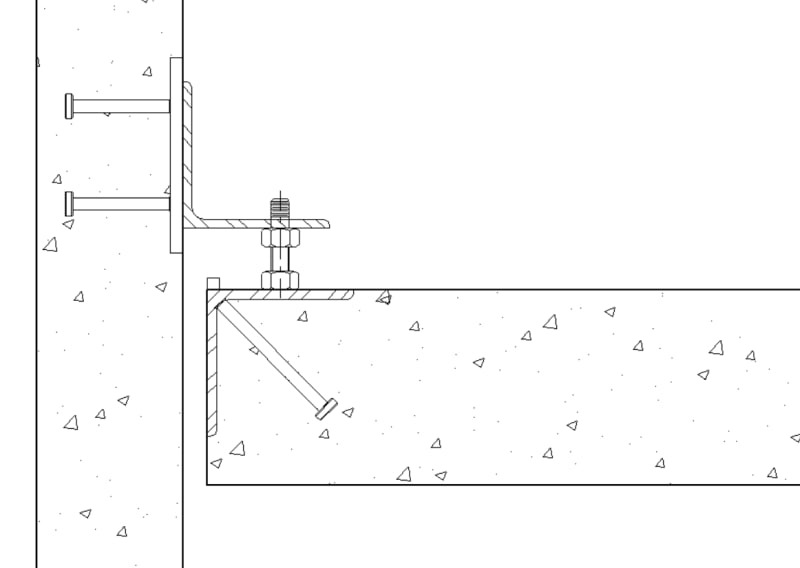
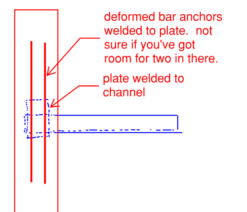
- Parapets will have a 900 mm (35.4 in) long UPE steel U-channel (poking out) concreted in during the precasting phase.
- Balcony slabs will 2 HALFEN HTE anchor channels (per connection) concreted in during the precasting phase.
- Two precast elements will be bolted on site with HALFEN T-bolts.

The steel U-channel, HALFEN anchor channels and T-bolts are designed for ULS combinations considering wind loads.

I Would love to hear what do you guys think about my design conceptually, because I have not done a connection like this before.

I am attaching a JPEG sketch
 
 https://files.engineering.com/getfile.aspx?folder=c6e80e03-aab4-4a81-9e34-46dd51f1fe03&file=UPE_connection_B.jpg
Replies continue below

Recommended for you

I would suggest ;

- Delete the Halfen anchor channel near the PC Parapet . You just need one anchor channel and tension bolt at far side ..

- If the sketch , ( isometric view ) is scaled, UPE section seems around UPE 300 ..You do not need such a heavy section

- provide recess at RC slab ..

Apparently you are familiar with HALFEN..

Pls look to the parapet corbel PP 20-24 of the attached doc.

parapet_pc_corbel_detail_mooluj.jpg


My opinion only..


Don't underestimate a nail. A nail saves a horseshoe, a horseshoe saves a horse, a horse saves a commander, a commander saves an army, an army saves a whole country.. GENGHIS KHAN
 
@HTURKAK

Thanks for your input HTURKAK.

I have been in contact with HALFEN people trying to make their product (BRA Corbel, the one you sent) work, but they are hesitant to green light it,
because there will be glass paneling above the parapet (they are worried because their product has a lower-ish bending stiffness and a dislocation of panels under deflection could occur).

Anyway so my next step was to kinda borrow their concept, only I will use UPE U-channels (higher bending stiffness) instead of their product.

The wind pressure is in places high enough to create tension on the pressure pad side believe it or not, hence I used two anchor channels.

Those are UPE 180, the CAD just makes it looks so big I guess.


This is not a matter of belief.. Engineers should look to the calculations or perform analysis to make sure..


Don't underestimate a nail. A nail saves a horseshoe, a horseshoe saves a horse, a horse saves a commander, a commander saves an army, an army saves a whole country.. GENGHIS KHAN
 
I haven't done these for a while (decades) but we used to put a weld plate on the precast panel, and cast an inverted section of angle into the slab edge. They were secured by headed studs. The angle had a BAR 1/2X1/2 welded to the outside edge.

A clip angle was welded to the precast weld plate. This angle had a high strength bolt installed so the head could be used for levelling. The precast panel was erected in place and temporarily secured to the columns and the levelling bolts were adjusted to level the panel. The purpose of the bar at the end was to prevent the panel from slipping off the slab connection angle. This minimised the amount of time the crane had to be in place, holding the panel.

The assembly attachment shown is difficult and intrudes into the precast panel assembly, and may get damaged during movement from the precast plant to the site and there is no latitude for adjustment.

-----*****-----
So strange to see the singularity approaching while the entire planet is rapidly turning into a hellscape. -John Coates

-Dik
 
@dik

Hmm interesting, cant really imagine it, is it something like this (attachment) ?
I have a nagging feeling that my design could be overdone (although I spent quite some time working on it).
But considering high wind loads (pressure / suction) the design looks appropriate, although I agree the installation and transportation might be icky.
I planned to use obround holes and shims for on-site adjustments.

@HTURKAK

I agree.
PS: I was referring to my wind load study for the project, not talking in general (that would be rude).
 
 https://files.engineering.com/getfile.aspx?folder=7363ab23-8b8c-4928-b8f7-fd9602cb092f&file=angle_dik.jpg
something like... with the column attachments looking after the lateral loads.

Clipboard01_wqbrjh.jpg


-----*****-----
So strange to see the singularity approaching while the entire planet is rapidly turning into a hellscape. -John Coates

-Dik
 
@dik

That looks nice, but I am worried such a connection's rotational stiffness is somewhat small compared to what I designed.
Since this is for a 19 to 24 storey building with somewhat high wind loads, and my intention is to limit the deflections (glass panels on parapet), I would have to use many of these per parapet.

What would you say is the moment lever arm of your connection?
The height of the bolt?
 
the restraint occurs by the attachment at the ends.

-----*****-----
So strange to see the singularity approaching while the entire planet is rapidly turning into a hellscape. -John Coates

-Dik
 
CovertShear said:
Anyway so my next step was to kinda borrow their concept, only I will use UPE U-channels (higher bending stiffness) instead of their product.

I like your concept in general but feel that you ought to go even further with respect to mimicking the halfen setup. My concerns pertain to the use of the vertical channel piece embedded within the panel:

1) Will it be disruptive to the successful concreting of panel and, more importantly;

2) Will its flexibility be incompatible with the surrounding concrete.

When you look at a lot of common precast connection typologies that utilize steel hardware, a common theme is that they transition from structural steel to reinforced concrete as soon as practical. I believe that the reasoning for that is my #2 above. See the sketch below for what I consider to be an improved version of your scheme.

C01_mdrs81.png
 
@KootK

When you look at a lot of common precast connection typologies that utilize steel hardware, a common theme is that they transition from structural steel to reinforced concrete as soon as practical

Interesting, I did not know that, but it makes sense, especially the flexural incompatibility part.

Thanks for you design, I like it. Especially the plate welded to U-channel to which the rebar will be welded.
 
Status
Not open for further replies.
Back
Top