Eng-Tips is the largest engineering community on the Internet

Intelligent Work Forums for Engineering Professionals

Precast wall connection in bending 1

Status
Not open for further replies.

bugbus

Structural
Aug 14, 2018
498
0
0
AU
I have a situation where a short (~1.2 m) precast retaining wall would need to be installed on a cast in-situ footing. For various reasons that I won't go into, a cast in-situ wall may not be doable in this case.

I am exploring various options, including:

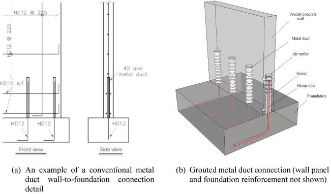
A) One similar to the picture below with reinforcement starter bars that slot into metal PT ducts and then grouted. Note that I would have two layers of reinforcement in the precast wall, with a single row of bars forming the connection.
B) Threaded rods projecting from the footing instead of reinforcement, slotted through the full height of the wall and bolted at the top, then the duct and recess grouted.
C) Same as B) but with 1030 Grade stress bars and some post-tensioning applied.

What is the performance of this type of precast wall connection for out-of-plane bending? Strength is no concern, as this will require relatively little reinforcement. My main concern would be that a fairly wide crack would open up at the base of the wall and cause a potential durability problem.

AS5100.5 (the code I need to use) states that walls >150 mm thick need to have 2 layers of reinforcement (one at each face). In my case, this would be satisfied within the precast wall itself, but not in the plane of the connection. Is this allowable?

Regarding the spacing of the bars forming the connection, am I also forced to stick to the 300 mm limit for walls? With a 2.4 m long wall segment, would it be particularly onerous to have to align 8 bars to slot into the wall?

1-s2.0-S0141029618308460-gr1_ci10do.jpg
 
Replies continue below

Recommended for you

I've used that type of metal conduit for moment connections, but not for major retaining wall type connections; they work well and you can develop the bar. I don't know why the client would be concerned about having the footing as part of the retaining element? It seems like a natural extension with no downside. It should be easy enough to level a bearing surface to be 'flat' for the extent of the wall.

Vertical joints may be a problem if in freezing climate.

Rather than think climate change and the corona virus as science, think of it as the wrath of God. Feel any better?

-Dik
 
I agree with ISD, the durability concerns are real issue.


I can remember only 15 years back the masonry guys calling local engineers in my area and making sure that people understood that a crack would likely develope at the interface and that we should consider water proofing and galv bars in all rw's including civil. In this case there will be nothing but bar so way worse, and stainless steel reo isn't going to be cheap.
 

to my mind the solution depends on loads. use of grouted ducts is pretty common in my experience and can develop full anchorage. anchoring/stressing them down seems heavy handed unless the loads require it.

there is some useful info in the NZ standards / publications of detailing around the grout ducts to give some ductiliy to them, basically a set of square column type ties around each duct with 4 longitudinals. this is common in NZ

to assist durability, galvanised starters may assist. any chance of some applied waterproofing or even a hydrophillic strip to assist. i would be keeping the stresses very low and using this to assist in keeping cracks to a minimum and giving some ductility. If that means 300mm spacings, so be it.
 
The other way I've seen this type of connection being installed, is instead provide the wall sitting on some bearing plates and propped back to beyond the footing footprint, horizontal drossbach ducts are detailed through the panel (say at 200-300 ctrs), through which top and bottom footing reinforcement is passed and lapped. Then pour footing on either side sandwiching the panel. Embedded section of wall is prepared in the yard with retarder so it is intentionally roughened. This way both layers of wall reinforcement can effectively go into the footing.

An alternative to this theme is just have a few sections of panel that extend to the underside of the footing to be supported on smaller concrete bearing pads. Then the wall cage protrudes into the footing from the bottom edge of the panel over the remainder. Organise your footing cage so this complete panel with projecting U bar starters can just be dropped into the footing cage onto the bearing pads. Adjust footing cage once panel is propped then pour footing under and marginally up the panel for a construction that is near equivalent to a monolithic cast in place reinforcement arrangement (just poured the opposite way with footing following the wall.

 
Bit of an old thread but i'll add my 2 cents.

"AS5100.5 (the code I need to use) states that walls >150 mm thick need to have 2 layers of reinforcement (one at each face). In my case, this would be satisfied within the precast wall itself, but not in the plane of the connection. Is this allowable?" This requirement was bought in after the Christchurch earthquake, many single layered walls / fin columns failed abruptly, so they brought this in to ensure a minimum amount of ductility. You should have no in plane load from your sketches, so the requirement is null and void. There is commentary in a AS 1170.4 discussion paper with the guy's behind the standard regrading tilt up walls, that is in industrial type buildings (no suspended slabs, low axial load) the double layer of reo is not required as there is enough movement / flexibility between panels it's not required as the walls will not fail in a sudden manner.

"My main concern would be that a fairly wide crack would open up at the base of the wall and cause a potential durability problem."
I would grout the base (similar to a tilt up wall) and use galvanised reinforcing (for starter bars).
 
@bodgy engineer - can you give some guidance on the AS1170.4 discussion paper you mention, ie author or how to get it? am curious about the tilt-up industrial buildings. Thanks
 
Status
Not open for further replies.
Back
Top